2-7
2-2 Wiring
2
Design
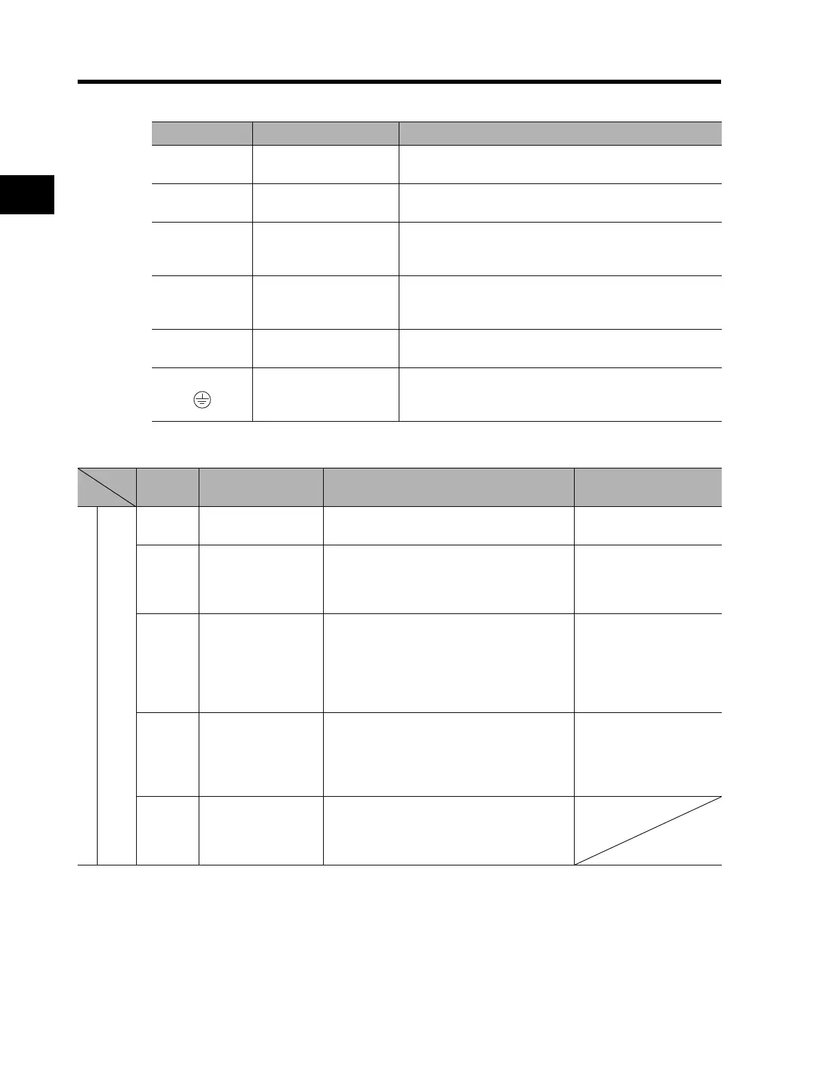
Main Circuit Terminals
Control Circuit Terminal
Terminal symbol Terminal name Description
R/L1, S/L2,
T/L3
Main power supply input
terminal
Connect the input power supply.
U/T1,V/T2,
W/T3
Inverter output terminal Connect to the 3-phase motor.
+1, P/+2 External DC reactor
terminal
Remove the short-circuit bar between terminals "+1" and
"P/+2", and connect the optional power factor
improvement DC reactor.
P/+2, RB Braking resistor
connection terminals
Connect optional external braking resistors. (The RB
terminal is provided for the Inverters with 22 kW or lower
capacity.)
P/+2, N/- Regenerative braking
unit connection terminal
Connect optional regenerative braking units.
G Ground terminal Inverter case ground terminal. Connect this terminal to the
ground.
type-D (200-V class), type-C (400-V class)
Terminal
symbol
Terminal name Description Specifications
Analog
Frequency reference input
FS Frequency reference
power supply output
+10 V DC power supply for the FV terminal. Allowable load current:
20 mA max.
FV Frequency reference
input
(Voltage directive)
With a 0 to 10 V DC voltage input, the
frequency reaches the maximum at 10 V.
Set at A014 if the maximum frequency
needs to be achieved at lower than 10 V.
Input impedance 10 kΩ
Allowable input voltage
range:
-0.3 to +12 V DC
FE Auxiliary frequency
reference input
(Voltage directive)
With a 0 to ±10 V DC voltage input, the FE
signal is added to the frequency reference
signal of the FV or FI terminal. By changing
the setting, the frequency reference can be
input even with the FE terminal
independently.
Input impedance 10 kΩ
Allowable input voltage
range:
0 to ±12 V DC
FI Frequency reference
input
(Current directive)
With a 4 to 20 mA DC current input, the
maximum frequency is set at 20 mA. The FI
signal is only active when the AT terminal is
ON. Allocate the AT function to the multi-
function input terminal.
Input impedance 100 Ω
Allowable max. current:
24 mA
FC Frequency reference
common
Common terminal for the frequency setting
signals (FV, FE and FI) and the analog
output terminals (AM and AMI). Do not
connect this terminal to the ground.
Continued to the next page