2-22
2-2 Wiring
2
Design
Wiring Control Circuit Terminals
• Terminals FC and SC are insulated from each other via the input and output signal common
terminals.
Do not short-circuit or ground these common terminals.
Do not ground these common terminals via external equipment. (Check the external equipment
ground conditions.)
• For wiring the control circuit terminals, use twisted shielded cables (recommended size: 0.75
mm
2
), and connect the shielded cable to each common terminal.
• The control circuit terminal connection cables should be 20 m or less.
• Separate the control circuit terminal connection cable from the main circuit cable (power cable)
and the relay control circuit cable.
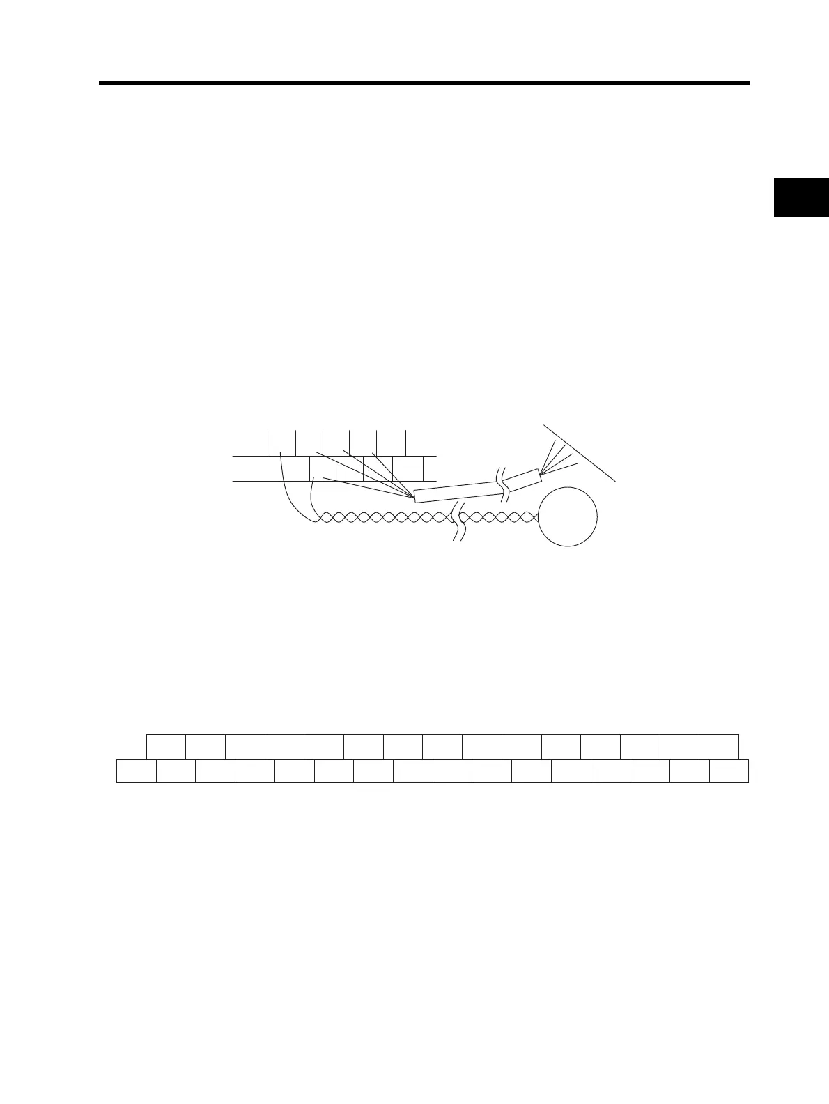
• For the connection of the TH (thermistor input) terminal, twist cables with the terminal SC
individually, and separate them from other SC common cables.
Since a weak current flows through the thermistor, the thermistor connection cable must be
separated from the main circuit cable (power cable). The thermistor connection cable should be
20 m or less.
• To use a relay for the multi-function output terminal, connect a surge-absorbing diode in parallel
with the coil.
• Do not short-circuit the analog power supply terminals (between FS and FC) and/or the interface
power supply terminals (between P24 and SC).
Doing so may result in failure of the Inverter.
Arrangement of the Control Circuit Terminal Block
Selecting the Input Control Logic
By factory default the terminal FW and the multi-function input terminal are set to sink logic (NPN).
To change the input control logic to source logic (PNP), remove the short-circuit bar between the
terminals P24 and PSC on the control circuit terminal block, and connect it between the terminals
PSC and SC.
TH FW S8 SC S5
PSC SC S7
S6 S4
Thermistor
PLC
FS FE AM MP TH FW S8
SC S5 S3 S1 P4 P3 P1 MA
FC FV FI AMI P24 PSC SC
S7 S6 S4 S2 P5 PC P2 MC MB
Terminal screw size M3 Tightening torque 0.7 N·m (0.8 max.)