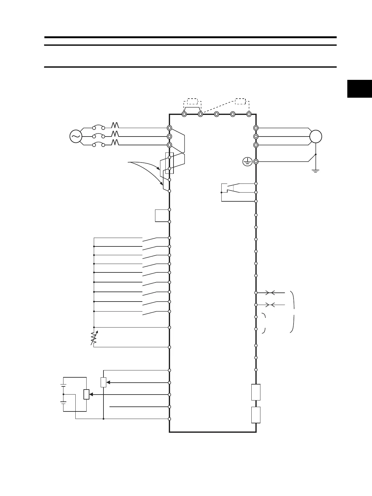
DC reactor
(optional)
3-phase 200 V AC
3-phase 400 V AC
Multi-function input 1
Multi-function input 2
Multi-function input 3
Multi-function input 4
Multi-function input 5
Multi-function input 6
Multi-function input 7
Multi-function input 8
Frequency reference power supply
Frequency setting unit
500 to 2 kΩ
Frequency reference input (voltage)
Frequency reference auxiliary input (voltage)
Frequency reference input (current)
Frequency reference common
*1. By default, MA is set to NC contact, and MB to NO contact in the relay output (MA, MB)
contact selection (C036).
Sequence input common
M
R/L1
+1 P/+2
Braking resistor
(optional)
RBN/-
T/L3
R
T
Ro
To
S/L2
U/T1
W/T3
P2 Multi-function output 2
P3 Multi-function output 3
P4 Multi-function output 4
P5 Multi-function output 5
PC
RS+
RS-
RP
RS-
AM
AMI
MP
Option 1
Option 1
Multi-function output common
P1 Multi-function output 1
Relay output *1
Common
V/T2
S1
FW
P24
PSC
S4
SC
Thermistor
TH
FS
FI
FC
FV
FE
S3
S2
S5
RS485 communication
S6
S7
S8
Short-circuit
wire
To wire the control circuit power
supply and main circuit power
supply separately, be sure to
remove the J51 connector
wire first.
(Refer to page 2-21)
Control circuit
power supply
J51
For termination
resistors
Analog monitor output
(voltage output)
Analog monitor output
(current output)
Digital monitor output
(PWM output)
MB
MA
MC