5-5
5-1 Protective Functions and Troubleshooting
5
Maintenance Operations
Brake error
When 01 is selected in b120 (brake
control selection), this error appears
if the brake ON/OFF cannot be
confirmed within the b124 set time
(brake confirmation wait time) after
the Inverter outputs the brake
release signal.
Is the brake ON/OFF function working?
(Brake check)
Is the set time for b124 too short?
(Increase b124.)
Has the brake confirmation signal been
input?
(Wiring check)
4-73
Emergen-
cy shutoff
*2
Shuts off the hardware output and
displays an error when the EMR
terminal (S3) is turned on with SW1
on the logic board ON.
Did any error occur in the external
devices when the emergency shutoff
function was selected?
(Correct the external device error.)
2-10
Overload
trip in low
speed
range
If an overload is detected in the
lowest speed range of 0.2 Hz max.,
an electronic thermal inside the
Inverter works to shut off the Inverter
output. (2nd electronic thermal)
(However, higher frequency could
remain in the error history.)
Is the load too large? (Reduce the loading
factor.)
4-49
4-50
ModBus
communic
ations error
Appears when the timeout occurs
because of disconnection during
Modbus-RTU communication.
(Trip by the C076 setting)
Is the communication speed correct?
Is the wiring distance appropriate?
(Connection check)
4-139
Option 1
error
Detects an error on the board
mounted on option port 1.
to
Has the option board been securely
mounted?
(Check that the mounting is correct.)
Option 2
error
Detects an error on the board
mounted on option port 2.
to
Has the option board been securely
mounted?
(Check that the mounting is correct.)
Undervoltage
standby
Shows the waiting status after the
incoming Inverter voltage decreases
and shuts off.
This error also appears during
momentary power interruption.
Has the power supply voltage dropped?
(Power recovery)
Is there a contact failure for MCB and/or
Mg?
(Replace MCB, Mg.)
Is the voltage between P and N normal?
(Check the voltage between P and N.)
Communications
error
Appears if an error occurs between
the Digital Operator and the
Inverter.
Has the relay plug been inserted
properly?
(Check the relay plug contact.)
Has the Digital Operator been inserted
properly?
(Check the Digital Operator contact.)
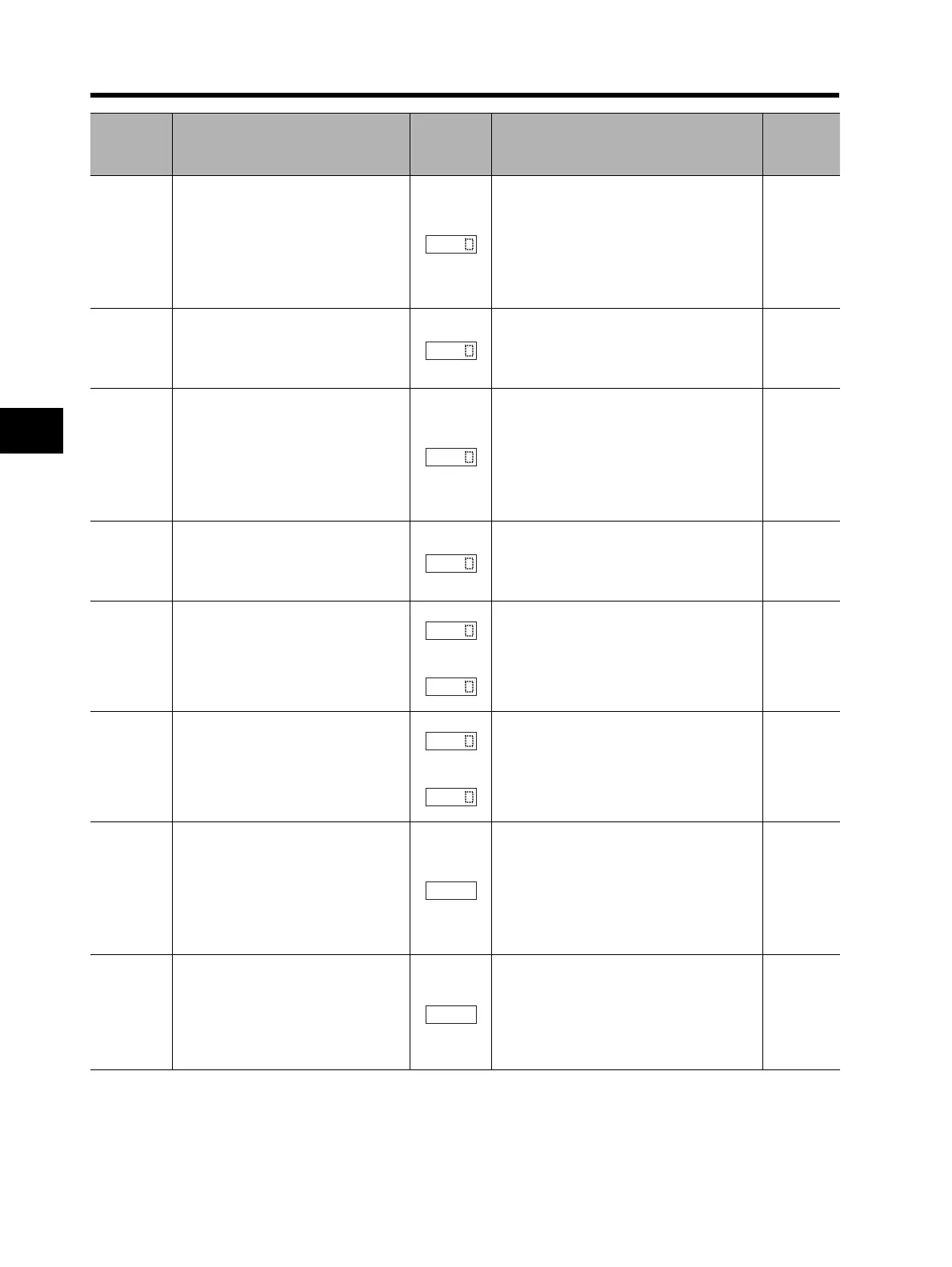
Name Description
Display on
Digital
Operator
Check point and remedy
Reference
page
*1. The reset command through the RS terminal or STOP/RESET key is not accepted. Turn off the power.
*2. The reset operation via the Digital Operator is not accepted. Be sure to reset via the RS terminal.
 Loading...


