32
Examples
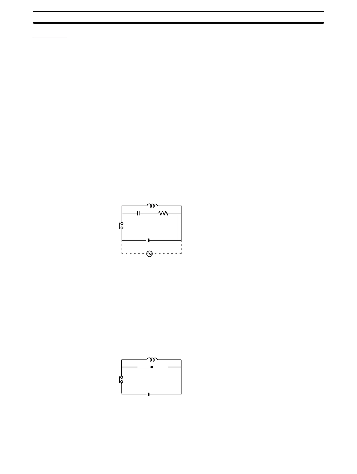
Connect a surge suppressor or diode in parallel with the load, as shown in the
following diagrams, when switching inductive loads.
CR Method (AC or DC)
The reset time will be increased if the load is a relay, solenoid, or similar device.
Connect the CR between the load connections for 24-V and 48-V power supply
voltages and between the contact connections for 100 to 200-V power supply
voltages.
The capacitor and resistors can be based on the following guidelines.
C: 0.5 to 1 µF for each amp of contact current
R: 0.5 to 1 Ω for each volt of contact voltage.
You will need to adjust the above values depending on the characteristics of the
load, relay, etc., based on the discharge suppression of the capacitor when the
contacts are open and the current control effect of the resistor the next time the
circuit is closed.
The dielectric strength of the capacitor generally needs to be between 200 and
300 V. Use an AC capacitor (without polarity) in an AC circuit.
Inductive load
CR
Power supply
Diode Method (DC Only)
The energy stored in the coil is impressed on the coil as a current by the action of
the parallel diode and converted to Joule heat by the resistance of the inductive
load. Here, the reset time will be increased even more than for the CR method.
The reverse dielectric strength of the diode must be 10 times the circuit voltage
and the forward current must be at least as high as that of the load. If the circuit
voltage is low enough, as it is for most electronic circuits, then the reverse dielec-
tric strength of the diode can be as low as 2 to 3 times the circuit voltage.
Inductive load
Power supply
Varistor (AC or DC)
The method uses the fixed voltage characteristics of a varistor to prevent high
voltages from being applied to the contacts. Here, as well, the reset time will be
increase somewhat.
Inductive Load Surge
Suppressor
Wiring and Connections
Section 2-5
Artisan Technology Group - Quality Instrumentation ... Guaranteed | (888) 88-SOURCE | www.artisantg.com