!
!
28
2-5-4 I/O Unit Wiring
Note To satisfy the EC directives (low-voltage directives), provide reinforced insula-
tion or double insulation for the DC power supply used with the I/O Unit.
The following information must be considered when connecting electrical
devices to I/O Units.
Caution Tighten the terminal screws to a torque of 0.5 to 0.6 N S m.
WARNING Do not apply voltages exceeding the input voltages to Input Units nor voltages
exceeding the switching capacity to Output Units. Doing so may result in
damage or destruction of the I/O Unit or result in fire.
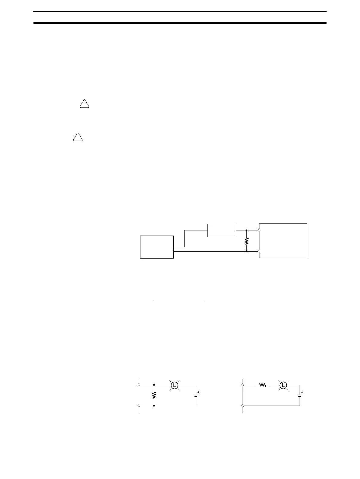
Leakage Current (24 VDC) A leakage current can cause false inputs when using 2-wire sensors (proximity
switches or photoelectric switches) or limit switches with LEDs on 24 VDC.
If the leakage current exceeds 1.3 mA, insert a bleeder resistor in the circuit to
reduce the input impedance, as shown in the following diagram.
R
SYSMAC
Input power
supply
Bleeder resistor
2-wire method
sensor, etc.
R = 7.2/(2.4I–3) kΩ max.
W = 2.3/R W min.
I: Device’s leakage current (mA)
R: Bleeder resistance (kΩ)
W: Bleeder resistor’s power rating (W)
The equations above were derived from the following equation:
W ≥ Input voltage (24)/R Input voltage (24) tolerance (4)
I
R
Input voltage (24)
Input current (10)
R +
Input voltage (24)
Input current (10)
≤ OFF voltage (3)
Inrush Current The following diagram shows two methods that can be used to reduce the large
inrush current caused by certain loads, such as incandescent light bulbs.
R
OUT
COM
OUT
COM
R
Example 1 Example 2
Generating a dark current (about 1/3 of the
rated current) through the incandescent bulb.
Inserting a regulating resistance.
Be careful not to damage the output transistor.
Wiring and Connections
Section 2-5
Artisan Technology Group - Quality Instrumentation ... Guaranteed | (888) 88-SOURCE | www.artisantg.com