!
29
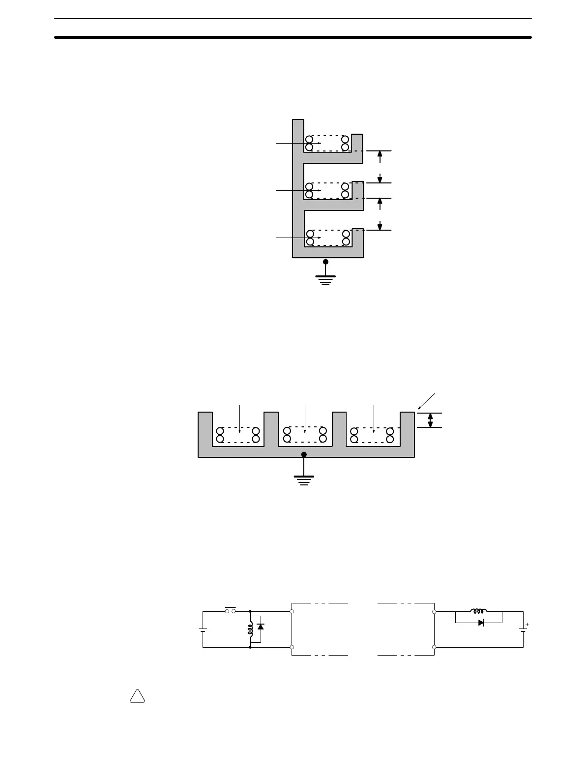
I/O Line Noise Do not run CQM1 I/O lines in the same duct or conduit as multi-conductor cables
of other control lines. If power cables carry more than 10 A at 400 V or more than
20 A at 220 V, they must be run parallel to I/O wiring. Leave at least 300 mm
between the power cables and the I/O wiring, as shown in the following diagram.
Low current cables
Control cables and
CQM1 power lines
Power cables
300 mm min.
300 mm min.
Grounding at resistance
of 100 W
max.
If the I/O wiring and power cables must be placed in the same duct (for example,
where they are connected to the equipment), shield them from each other using
grounded metal plates. In addition, use shielded cables for the I/O signal lines to
improve noise immunity. Also, connect the shielded cables to the GR terminal of
the PC.
200 mm min.
Grounding at resistance
of100 W max.
Metal plate (iron)
Low current cables
Control cables and
CQM1 power lines
Power cables
Inductive Loads When connecting an inductive load to an I/O Unit, connect a diode in parallel with
the load. The diode should satisfy the following requirements:
1, 2, 3... 1. Peak reverse-breakdown voltage must be at least 3 times the load voltage.
2. Average rectified current must be 1 A.
IN
COM
OUT
COM
Diode
DC input
Contact output
Transistor output
Diode
Inputs Outputs
Caution Do not apply a voltage exceeding the maximum permissible input voltage of the
Input Unit or the maximum switching capacity of the Output Unit, otherwise the
Units may be damaged, a malfunction may occur, or a fire may result.
Wiring and Connections
Section 2-5
Artisan Technology Group - Quality Instrumentation ... Guaranteed | (888) 88-SOURCE | www.artisantg.com