30
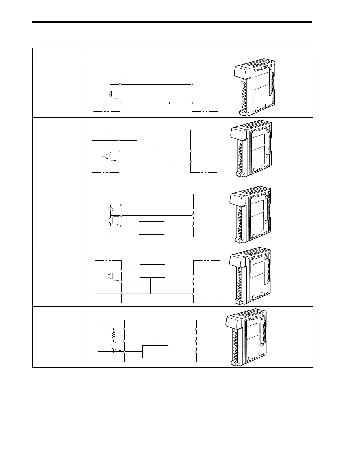
Input Devices When connecting an external device with a DC output to a DC Input Unit, wire
the device as shown in the following table.
Device Circuit Diagram
Contact output
IN
COM(+)
Relay
NPN open collector
0 V
+
IN
COM(+)
Sensor
Sensor power
supply
Output
NPN current output
Sensor power
supply
0 V
+
IN
COM(+)
Constant current
circuit
Output
Use the same power supply for
the input and sensor.
+
PNP current output
Sensor power
supply
COM(–)
0 V
IN
+
Output
Voltage output
Sensor power
supply
IN
COM (+)
0 V
Output
The following conditions must be met when using a 2-wire DC sensor input from
a 12-/24-VDC input device. Malfunctions will occur if these connections are not
met.
1, 2, 3... 1. The relationship between the PC’s ON voltage and the sensor’s residual
voltage must be as follows:
V
ON
≤ V
CC
– V
R
Precautions in Connecting
2-wire DC Sensors
Wiring and Connections
Section 2-5
Artisan Technology Group - Quality Instrumentation ... Guaranteed | (888) 88-SOURCE | www.artisantg.com