33
Connect the varistor between the load connections for 24-V and 48-V power
supply voltages and between the contact connections for 100 to 200-V power
supply voltages.
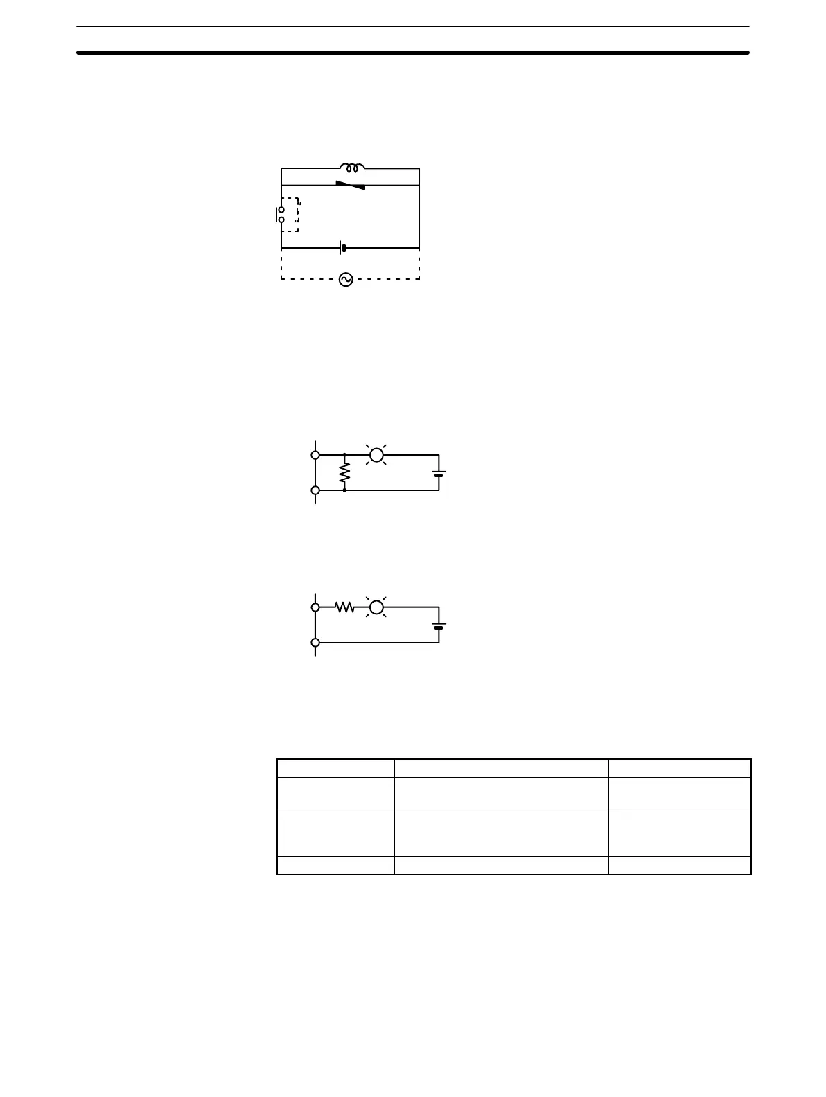
Inductive load
Power supply
Output Surge Current When connecting an output device having a high surge current (such as an
incandescent lamp), use one of the following circuit configurations to protect the
Output Unit.
The following circuit lets the load draw a small current (about one third the rated
current) while the output is OFF, significantly reducing the surge current.
OUT
COM
L
R
+
The following circuit reduces the surge current by employing a current-limiting
resistor.
LOUT
COM
+
R
2-5-6 Cable Preparation (Connector Type)
Prepare the cable for connector-type I/O Units as explained below.
Connector type Model (by Fujitsu) Set (from OMRON)
Soldered Socket: FCN-361J040-AU
Connector cover: FCN-360C040-J2
C500-CE404
Crimp Housing: FCN-363J040
Contact: FCN-363J-AU
Connector cover: FCN-360C040-J2
C500-CE405
Pressure welded FCN-367J040-AU/F C500-CE403
A soldered-type socket and connector cover are provided with each I/O Unit.
Recommended Wire Use AWG26 to 24 (0.2 to 0.13 mm
2
) wire for connecting to all of the connector
pins.
Note For details on pin arrangement and the internal circuitry of connectors at the
CQM1 side, refer to the sections on DC Input Units (32 points) and Transistor
Output Units (32 points) in this manual.
Recommended Connectors
(Cable Side)
Wiring and Connections
Section 2-5
Artisan Technology Group - Quality Instrumentation ... Guaranteed | (888) 88-SOURCE | www.artisantg.com