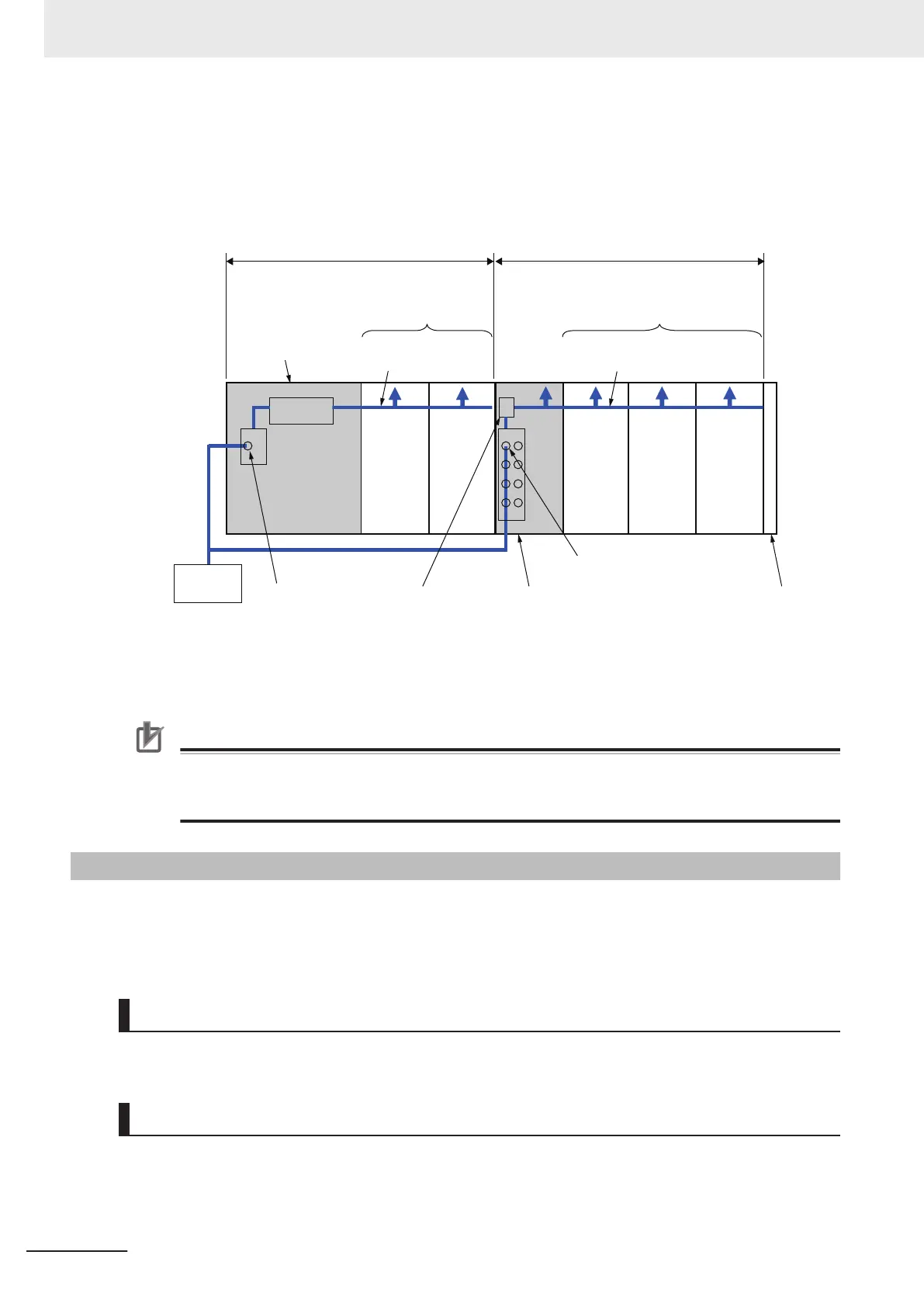
The following shows the Unit that supplies NX Unit power and its supplying range. For example,
the CPU Rack in the following diagram is configured with two blocks: the Communication Control
Unit block and the Additional NX Unit Power Supply Unit block.
Internal power
supply circuit
Communication Control Unit
block
Additional NX Unit Power Supply
Unit block
NX Unit connected to the
Additional NX Unit Power
Supply Unit
Additional NX Unit Power Supply Unit
Unit power supply
terminals
NX Unit connected to
the Communication
Control Unit
Unit power supply terminals
End Cover
Unit power
supply
NX Unit power supplyNX Unit power supply
Communication
Control Unit
Internal power
supply circuit
The total Unit power supply capacity for these two blocks is the power supply capacity that the
CPU Rack requires.
Precautions for Correct Use
Select a Unit power supply with sufficient capacity by considering the inrush current when the
power is turned ON. Sometimes, the Unit power supply may not be turned ON caused by inrush
current when the power is turned ON.
4-6-2
Wiring the Additional I/O Power Supply Unit
This section describes how to wire Additional I/O Power Supply Unit.
For the terminal array for each model, refer to the terminal connection diagram for each model in
A-1 Data Sheet on page A-2
.
Wiring Terminals
• I/O power supply terminals
Wiring Examples
The external power supply is connected to the A1 and A3 terminals of the I/O power supply terminals.
The other I/O power supply terminals can be used for power supply for connected external devices.
4 Installation and Wiring
4-32
NX-series System Units User's Manual (W523)