A-1
Data Sheet
The specifications of individual System Units are shown below.
A-1-1
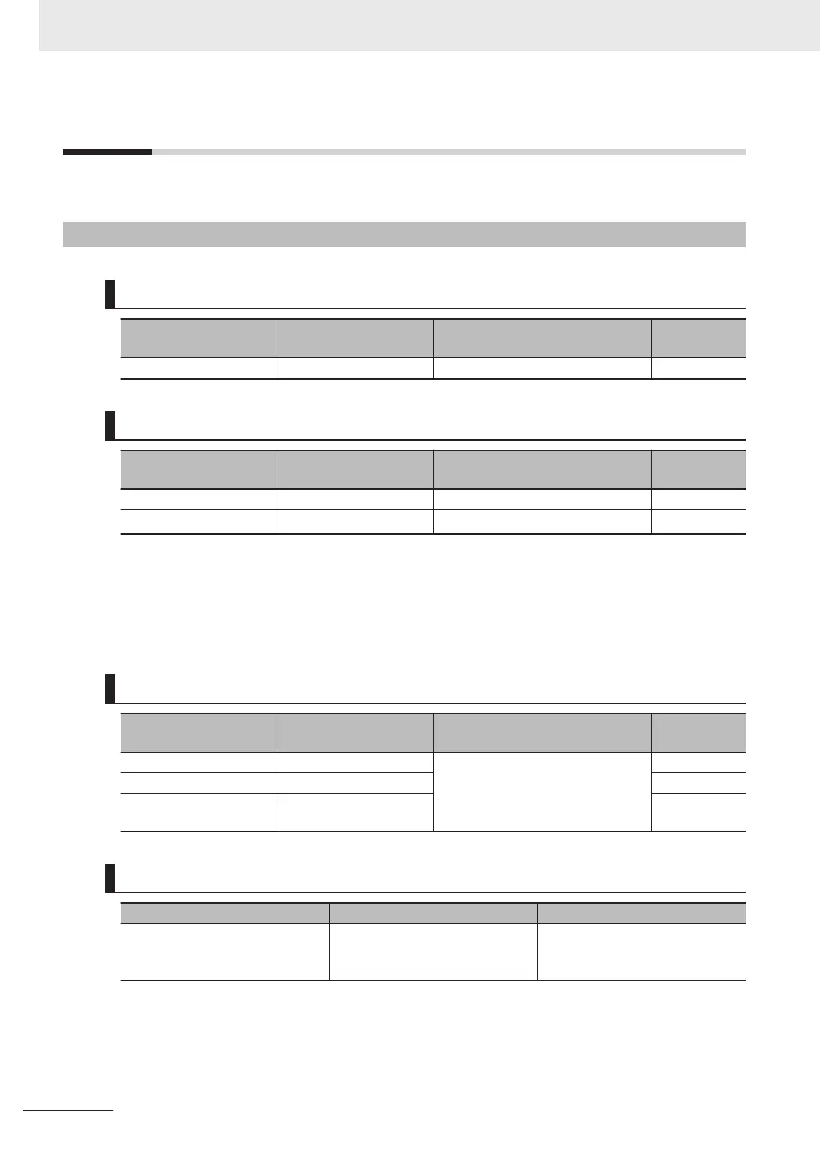
Model List
Additional NX Unit Power Supply Unit
Model
Rated power supply
voltage
NX Unit power supply capacity Reference
NX-PD1000 24 VDC 10 W max. page A-5
Additional I/O Power Supply Unit
Model
Rated power supply
voltage
Maximum current of I/O power
supply
Reference
NX-PF0630 5 to 24 VDC 4 A page A-9
NX-PF0730 5 to 24 VDC
10 A
*1
page A-11
*1. When an Additional I/O Power Supply Unit is connected to the CPU Rack of a CPU Unit, the maximum I/O
power supply current value may be smaller than that of the Additional I/O Power Supply Unit. For example,
the maximum I/O power supply current for the CPU Rack of an NX1P2 CPU Unit is 4 A. For the maximum
I/O power supply current of the CPU Rack, refer to Maximum I/O Power Supply Current under Designing the
I/O Power Supply from the NX Bus in the hardware user’
s manual for the CPU Unit to which NX Units are
connected.
I/O Power Supply Connection Unit
Model
Number of I/O power
supply terminals
Current capacity of I/O power sup-
ply terminal
Reference
NX-PC0020 IOV: 16 terminals 4 A/terminal max. page A-14
NX-PC0010 IOG: 16 terminals page A-16
NX-PC0030 IOV: 8 terminals
IOG: 8 terminals
page A-18
Shield Connection Unit
Model Number of shield terminals Reference
NX-TBX01 14 terminals
(The following two terminals are
functional ground terminals.)
page A-21
Appendices
A-2
NX-series System Units User's Manual (W523)