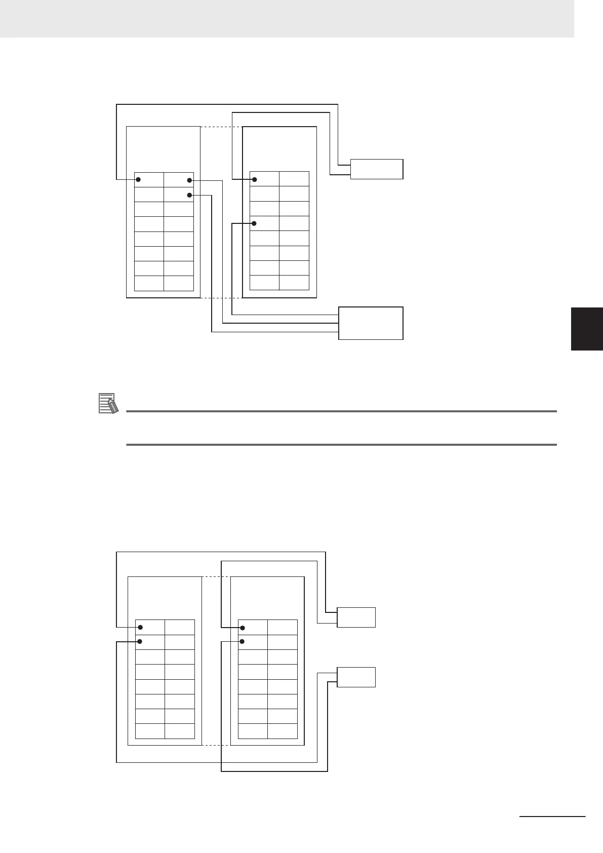
PNP type (NX-ID5442)
IOV
IOV
IOG
IOG
IOV
IOV
IOG
IOG
IOV
IOV
IOG
IOG
IOV
IOV
IOG
IOG
T
wo-wire sensor
(e.g. limit switch)
0
8
2
10
4
12
6
14
Digital Input Unit
(PNP type)
NX-ID5442
1
9
3
11
5
13
7
15
Three-wire sensor with
PNP output
(photoelectric sensor or
proximity sensor)
Brown (White)
Blue (Black)
Black (White)
Brown (Red)
Blue (Black)
A1
A8
B1
B8
A1
A8
B1
B8
I/O Power Supply
Connection Unit
NX-PC0030
(8 each of IOV/IOG
terminals)
Note
Connecting three-wire sensors to all 16 inputs requires two NX-PC0030 Units.
Additional Information
Wire colors have been changed according to revisions in the JIS standards for photoelectric
and proximity sensors. The colors in parentheses are the wire colors prior to the revisions.
Wiring Example 2
When the I/O Power Supply Connection Unit (NX-PC0020 or NX-PC0010) is connected to a Digital
Output Unit (16 outputs)
NPN type (NX-OD5121)
Solenoid, valve, etc.
0
8
2
1
0
4
12
6
14
I/O Power Supply
Connection Unit
NX-PC0020
(16 IOV terminals)
IOV
IOV
IOV
IOV
IOV
IOV
IOV
IOV
IOV
IOV
IOV
IOV
IOV
IOV
IOV
IOV
1
9
3
11
5
13
7
15
Solenoid, valve, etc.
A1
A8
B1
B8
A1
A8
B1
B8
Digital Output Unit
(NPN type)
NX-OD5121
4 Installation and Wiring
4-41
NX-series System Units User's Manual (W523)
4-7 Wiring the I/O Power Supply Connection Unit
4