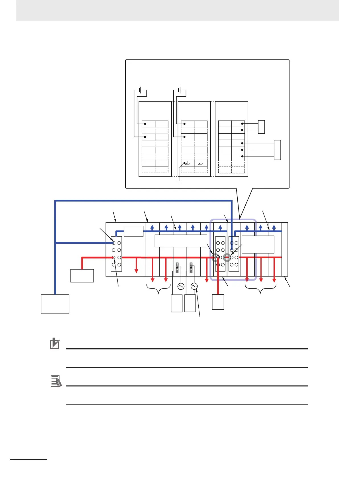
The following are wiring diagrams (examples) for each power supply.
Unit
power supply
(24 VDC)
I/O power
supply
External
output
device
I/O
power
supply
External
output
device
To external
devices
End CoverI/O power supply terminals
Unit power supply
terminals
Communications Coupler Unit
I/O power supply (Supply from external source)
NX Unit
Additional
NX Unit Power
Supply Unit
(Example) DC Input Unit
Two-wire
sensor
Three-wire
sensor
Additional I/O
Power Supply Unit
24 VDC Unit
power supply
24 VDC I/O
power supply
DC Input Unit
NX Unit
power supply
To external
devices
To external
devices
0
1
IOV IOV
2 3
IOV
IOV
IOG IOG
IOG IOG
UG
UV
UG
A1
A8
B1
B8
NC
NC
IOV
IOG
A1
A8
B1
B8
IOVIOV
IOG
IOG
A1
B1
A8
B8
IOV
IOG
The I/O power supply is
separated.
The I/O power
supply is not
separated.
Additional NX Unit
Power Supply Unit
Additional
I/O Power
Supply
Unit
NX Unit
power supply
Internal power
supply circuit
Precautions for Correct Use
Always use separate power supplies for the Unit power supply and the I/O power supply. If you
supply power from the same power supply, noise may cause malfunctions.
Additional Information
Refer to the user's manual for the Communications Coupler Unit on design for power supply to
the Slave Terminal.
4 Installation and Wiring
4-16
NX-series System Units User's Manual (W523)