Power supply
name
Description
I/O power sup-
ply
This power is supplied by one of the following two methods.
•
Supply from the NX bus
This power is supplied through the NX bus connectors by connecting an I/O power supply
to the I/O power supply terminals on the Communication Control Unit or Additional I/O Pow-
er Supply Unit.
•
Supply from external source
This power is supplied to the Units from an external source.
I/O power is supplied by connecting an I/O power supply to the I/O power supply terminals
on the Units.
For the supply method that you will use for an NX Unit model, refer to the data sheet in the
user’
s manual for the NX Unit or NX-series Data Reference Manual (Cat. No. W525).
Refer to A-1 Data Sheet on page A-2 for the supply method for each System Unit model.
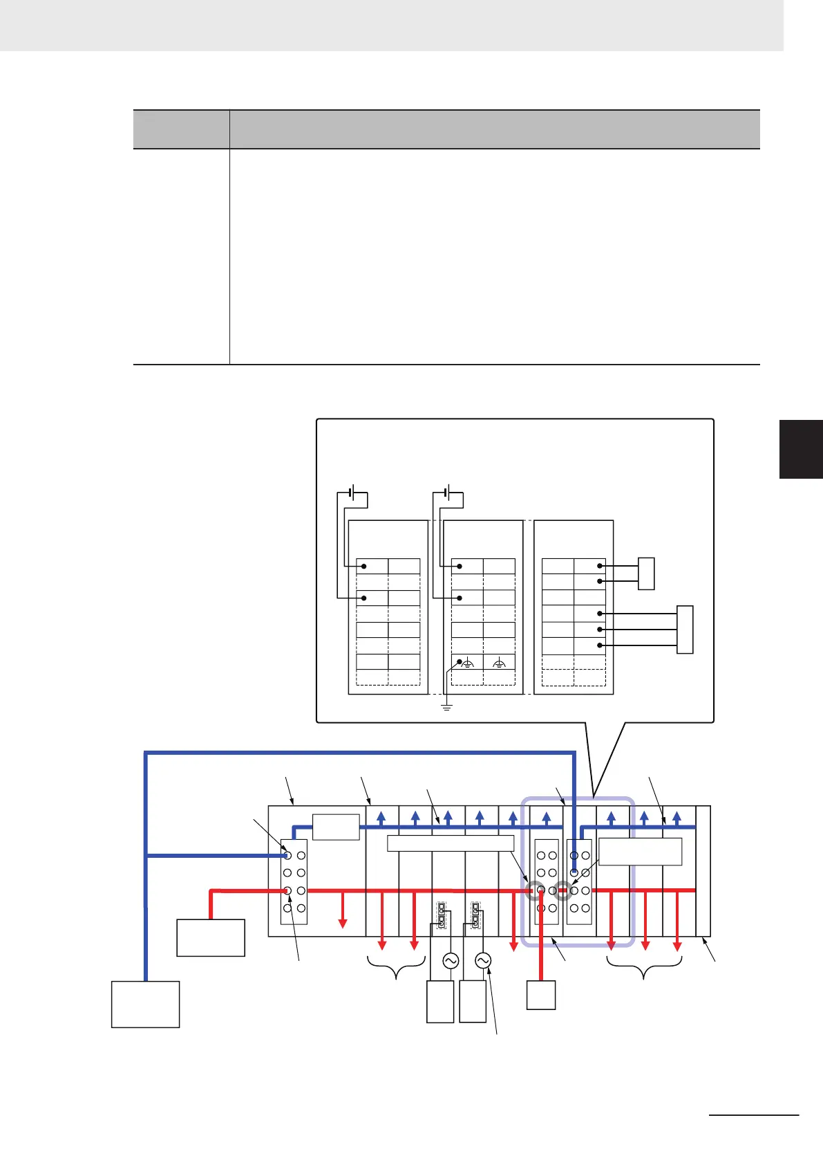
The following are wiring diagrams (examples) for each power supply.
Unit power
supply
(24 VDC)
I/O power
supply
Exter-
nal
output
device
I/O
power
supply
Exter-
nal
output
device
To external devices
To
external
devices
To external
devices
End Cover
I/O power supply
terminals
Unit power
supply terminals
Communication Control Unit
I/O power supply
(Supply from external source)
NX Unit
0
1
IOV IOV
2 3
IOV
IOV
IOG IOG
IOG IOG
UG
Additional NX Unit
Power Supply Unit
UV
UG
A1
A8
B1
B8
(Example) DC Input Unit
NC
NC
Two-wire
sensor
Three-wire
sensor
Additional I/O
Power Supply
Unit
IOV
IOG
A1
A8
B1
B8
IOVIOV
IOGIOG
24 VDC Unit
power supply
24 VDC I/O
power supply
A1
B1
A8 B8
Internal power
supply circuit
DC Input Unit
NX Unit
power supply
NX Unit power supply
IOV
IOG
The I/O power supply is separated.
The I/O power supply
is not separated.
Additional NX Unit
Power Supply Unit
Additional
I/O Power
Supply
Unit
4 Installation and Wiring
4-21
NX-series System Units User's Manual (W523)
4-4 Wiring the Power Supply to the Communication Control Unit
4
4-4-2 Supplying Each Power Supply and Wiring