26
SECTION 2
Connections and Wiring
CIDRW System
User’s Manual
SECTION 2
Installation and Connections/Wiring
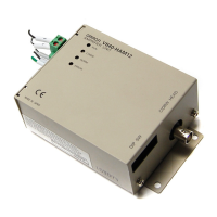
■ Ethernet Connector
1. Hold the connector on the cable and
insert it into the Ethernet connector on
the Amplifier Unit.
Press in the connector until it locks in place when connecting the Amplifier Unit to Ethernet, including when connecting
it to a hub.
• Connector
The Amplifier Unit provides an auto-MDIX function that enables communications by connecting either
a cross LAN cable or straight LAN cable.
The shape and dimensions of plugs and jacks for Ethernet connectors are specified in ISO/IEC 8877:1992 (JIS X
5110:1996) To prevent faulty connections for connectors, the jack on the Amplifier Unit is designed so that non-standard
plugs cannot be connected. If a commercially available plug cannot be connected, it may be non-standard.
If you use a Hub in your network, please choose a Switching-type Hub (Recommended: W4S1-05B(OMRON)).
Pin No. Signal name Description I/O
1 TX_D+ Send data + Output
2TX_D− Send data − Output
3 RX_D+ Receive data + Input
4 −−−
5 −−−
6RX_D− Receive data − Input
7 −−−
8 −−−
Recommended Ethernet HUB
Manufacturer Model Type Port
OMRON W4S1-05B switching hub 5
 Loading...