27
CIDRW System
User’s Manual
SECTION 2
Connections and Wiring
SECTION 2
Installation and Connections/Wiring
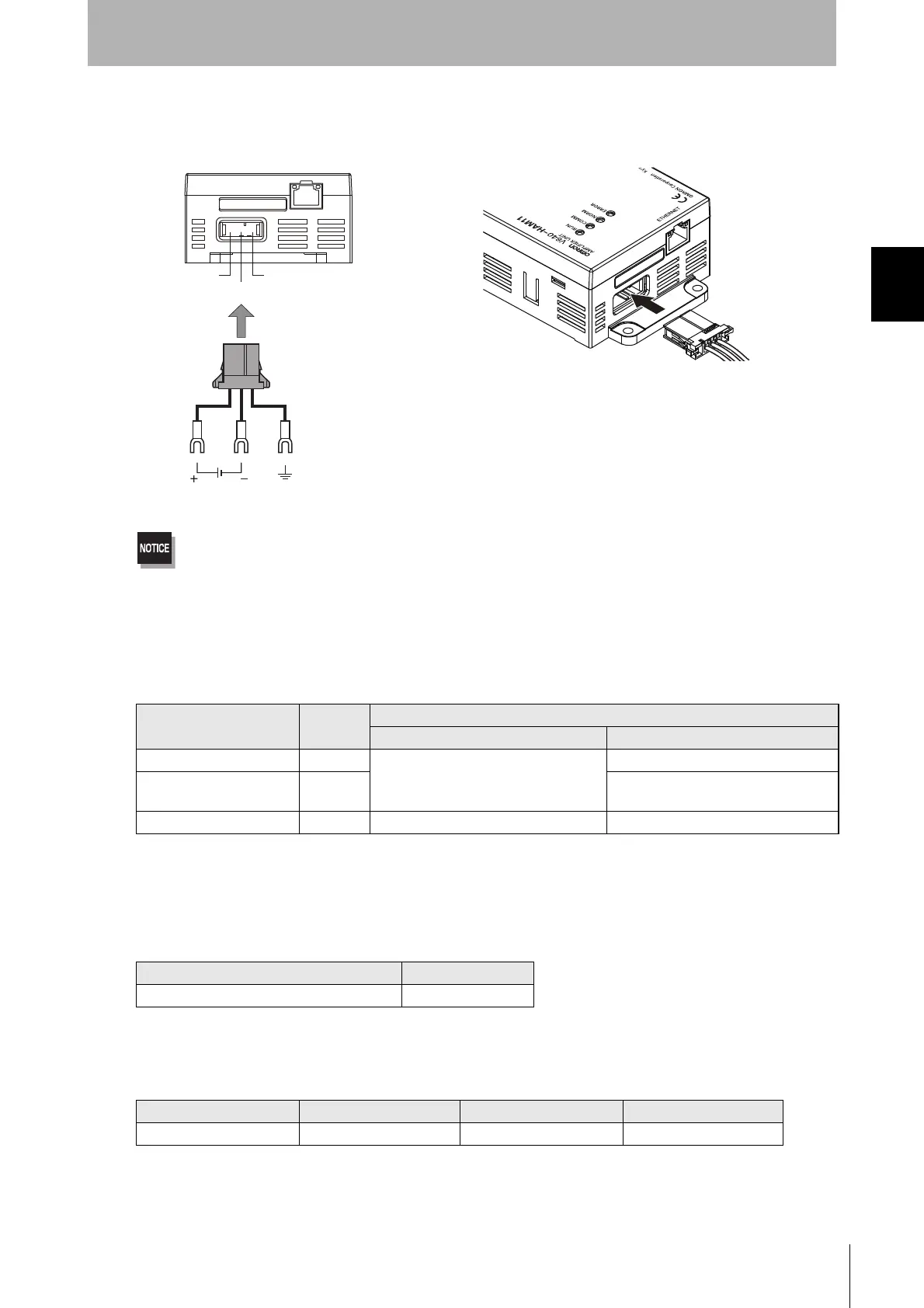
■ Power Supply and Grounding Wires
Connect the power supply and grounding wires to the dedicated power supply connector.
• The grounding wire should be connected to a ground exclusive to the Amplifier Unit. If the grounding wire is shared
with another unit, or connected to a beam in a building, there may be adverse effects.
• Make the grounding point as close as possible and the length of the grounding wire used as short as possible.
• When using the Amplifier Unit in Europe, the connecting cable between the Amplifier Unit and the DC power supply
must be 3 m or less.
• Dedicated Power Supply Connector
Prepare a V640-A90 (can be purchased as an accessory).
• Dedicated Power Supply Cable
Use an AWG20 to AWG24 cable.
Use a dedicated tool for crimping the cable to the connector pins.
• Power Supply
Use a power supply that satisfies the following conditions.
*The maximum power consumption of the Amplifier Unit is 150 mA at 24 VDC(V640-HAM11-V3), 400
mA at 24 VDC(V640-HAM11-L). The inrush current, however, must be considered when selecting the
power supply capacity. A power supply with an output of 650 mA min. at 24 VDC is recommended.
Contents of the V640-A90 set (accessory)
Name Quantity
When procured individually
Manufacturer Model
Power supply connector One Tyco Electronics 1-178288-3
Pins for power supply con-
nector
Three 175217-3
Connector for RS-485 port One Phoenix Contact MSTB2.5/2-STF-5.08
* “Connector for RS-485 port“ is not able to use for the Amplifier Unit.
Recommended Crimping Tool
Manufacturer Model
Tyco Electronics 919601-1
Recommended Product
Manufacturer Model Output current Input voltage
OMRON S8VS-01524 24 VDC, 650 mA 100 to 240 VAC
24 V+
24 V-
GR
24 VDC
Ground to 100 Ω or less
Connector
 Loading...