EasyManua.ls Logo

Omron V680 Series User Manual

Omron V680 Series
344 pages
To Next Page IconTo Next Page
To Previous Page IconTo Previous Page
Page #109 background imageLoading...
Page #109 background image
Section 6 RF Tag Communications
Section 6
Functions
107
RFID System
User's Manual
(Modbus TCP)
Normal RF Tag Communications
Communications with the RF Tag are performed by using the queries that are listed in the following
table.
Tag Memory Management
ï‚§ RF TAG OVERWRITE COUNT CONTROL Query
This query can be used to determine whether the RF Tag overwrite limit has been exceeded.
• With the RF TAG OVERWRITE COUNT CONTROL query with a subtraction specification, the
overwrite count is subtracted from the data in the user-specified overwrite count control area to
determine whether the number of overwrites has been exceeded.
• With the RF TAG OVERWRITE COUNT CONTROL query with an addition specification, the
overwrite count is added to the data in the user-specified overwrite count control area to determine
whether the number of overwrites has exceeded 100,000.
• The RF TAG OVERWRITE COUNT CONTROL query with an addition specification is designed for
use with an RF Tag write life of 100,000. The overwrite count control area must be set so that it is all
within one block.
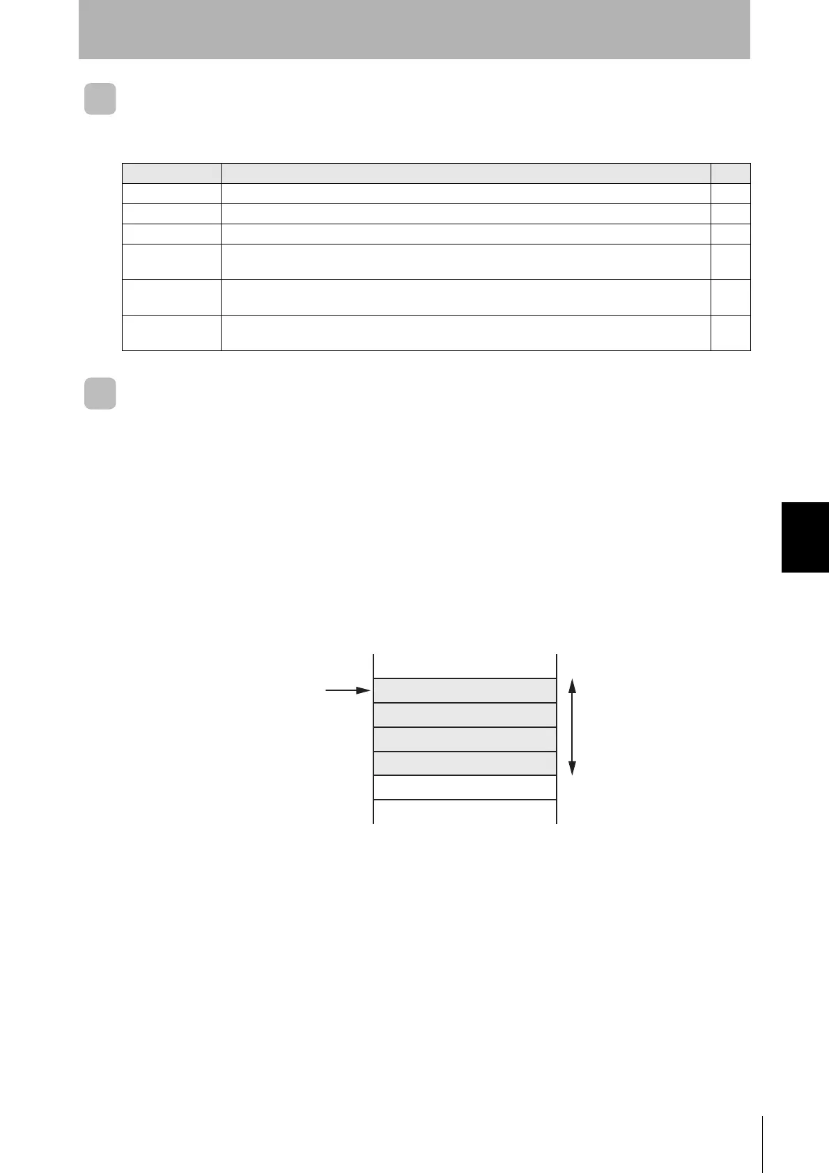
RF TAG OVERWRITE COUNT CONTROL Query with a Subtraction Specification
The overwrite count control area consists of 4 bytes from the specified start address. The decrement
value is subtracted from the overwrite count and then written to this area. When the value reaches 0
(i.e., 00 hex), a warning code is returned. Therefore, to enable control of the number of overwrites,
the maximum number of overwrites must be written to the overwrite count control area beforehand.
You can set any number of overwrites up to 16,700,000.
You can read the overwrite count control area with a read query. If the control area data is already 0,
the control area value will not be refreshed, and a warning code will be returned as a response.
When the refresh count is set to 0000 hex, the count will not be updated, and only an overwrite count
check will be performed.
Name Description Page
READ DATA Reads data from an RF Tag. p.170
WRITE DATA Writes data to the memory of the RF Tag. p.171
READ ID Reads the RF Tag’s ID code. p.172
DATA FILL Writes the specified data to the specified number of words beginning from the specified start
address. The specifications are made in the query.
p.175
LOCK Locks the specified memory block in the RF Tag. It will no longer be possible to write data to the
locked memory block. The lock cannot be released.
p.176
DATA COPY Reads data from the memory of an RF Tag using one Reader/Writer (A) and writes it to the
memory of the RF Tag in the communications field of another Reader/Writer (B).
p.173
2 words (4 bytes)
Overwrite count control area
Always 00 hex
Lower digit
Middle digit
Upper digit

Table of Contents

Questions and Answers:

Omron V680 Series Specifications

General IconGeneral
BrandOmron
ModelV680 Series
CategoryOther
LanguageEnglish

Summary

Introduction and Safety Precautions

Introduction

General information about the manual and product, including safety notices and trademarks.

Precautions for Safe Use

Essential guidelines for safe operation, installation, and handling of the Reader/Writer.

Precautions for Correct Use

Guidelines to prevent operational failures, malfunctions, and adverse effects on performance.

Product Overview and Specifications

Features

Highlights key features like integrated structure, simple installation, and stable operation.

Product Specifications

Detailed technical specifications for Reader/Writers, connector covers, cables, and RF Tags.

RF Tag Installation Precautions

Guidelines for optimal RF Tag mounting, considering metal influence and mutual interference.

System Configuration and Setup

System Configuration

Diagrams and descriptions of typical system setups with one or multiple Reader/Writers.

Installation and Connections

Procedures for installing the Reader/Writer and making necessary connections.

Preparations for Communications

Steps required to prepare the system, including starting the Reader/Writer and setting conditions.

Functions and Operation

Operation Mode

Describes Run Mode and Safe Mode for Reader/Writer operation based on control signal.

RF Tag Communications

Details on communication options (Once, Auto, FIFO) and methods with RF Tags.

Communication Diagnostic

Tool for diagnosing communication leeway for stable operation, displayed via indicators or web.

Multi-Reader/Writer Operation

Explains Field Extension and High-speed Traveling modes for linking multiple Reader/Writers.

Host Communications and Web Interface

Modbus Communications Protocol

Defines the client-server communication mechanism using Modbus TCP.

Web Browser Interface

Guide to accessing and utilizing the device's web interface for configuration and monitoring.

Network Settings View

Configuration of network parameters like IP address, subnet mask, and gateway.

Troubleshooting and Maintenance

Error Descriptions

Details on fatal and nonfatal errors, including indicator status and causes.

Troubleshooting Flowcharts

Step-by-step guides to diagnose issues based on system conditions and error types.

Maintenance and Inspection

Procedures for daily and periodic checks to ensure long-term product reliability.

Appendices

Data Characteristics

Reference data on RF Tag communications range and time.

Reader/Writer Installation Precautions

Guidelines for installing Reader/Writers, considering metal and mutual interference.

Related product manuals