SCALE.
GROUND
ON
MOTOR
AT
POINT
FREE
OF
GREASE
AND
PAINT
KNIFE
SWITCH
STORAGE
BATTERY
RESISTANCE
POSITION
OF j
BRAKE
ARM
-12"
STARTING
MOTOR
O
o
o
o
o
o
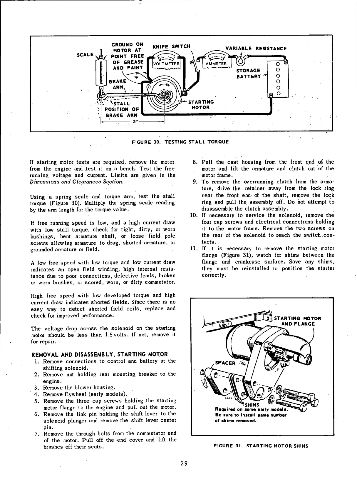
FIGURE
30.
TESTING
STALL
TORQUE
If
starting motor tests
are
required, remove
the
motor
from
the
engine
and
test
it on a
bench. Test
the
free
running voltage
and
current. Limits
are
given.
in the
Dimensions
and
Clearances Section.
Using
a spring
scale
and torque arm, test the
stall
torque (Figure 30).
Multiply
the spring
scale
reading
by
the arm length for the torque value.
If
free running
speed
is low, and a
high
current draw
with
low
stall
torque, check for
tight,
dirty,
or
worn
bushings, bent armature shaft, or loose
field
pole
screws
allowing
armature to drag, shorted armature, or
grounded armature or
field.
A
low free
speed
with
low torque and low current draw
indicates an open
field
winding,
high
internal resis-
tance
due to poor connections, defective leads, broken
or
worn
brushes, or scored,
worn,
or
dirty
commutator.
High
free
speed
with
low developed torque and
high
current
draw indicates shorted
fields.
Since there is no
easy
way to detect shorted
field
coils,
replace and
check for improved performance.
The voltage drop
across
the solenoid on the starting
motor
should be
less
than 1.5
volts.
If not, remove it
for
repair.
REMOVAL
AND
DISASSEMBLY,
STARTING
MOTOR
1.
Remove connections to
control
and battery at the
shifting
solenoid.
2.
Remove nut
holding
rear mounting breaker to the
engine.
3. Remove the blower housing.
4.
Remove
flywheel
(early models).
5. Remove the three cap screws
holding
the starting
motor
flange to the engine and
pull
out the motor.
6. Remove the
link
pin
holding
the
shift
lever to the
solenoid
plunger and remove the
shift
lever center
pin.
7. Remove the through bolts
from
the commutator end
of
the motor.
Pull
off the end cover and
lift
the
brushes
off their
seats.
8.
Pull
the
cast
housing
frpm
the
front
end of the
motor
and
lift
the armature and
clutch
out of the
motor
frame.
9. To remove the overrunning
clutch
from
the arma-
ture,
drive the retainer away
from
the
lock
ring
near
the
front
end of the shaft, remove the
lock
ring
and
pull
the assembly off. Do not attempt to
disassemble the
clutch
assembly.
10.
If
necessary
to service the solenoid, remove the
four
cap screws and electrical connections
holding
it
to the motor frame. Remove the two screws on
the rear of the solenoid to reach the
switch
.con-
tacts.
11.
If it is
necessary
to remove the starting motor
flange
(Figure 31), watch for shims between the
flange
and crankcase surface.
Save
any shims,
they must be reinstalled to position the starter
correctly.
STARTING
MOTOR
AND FLANGE
'SHIMS
Required
on
some
early
models.
Be
sure
to
install
same
number
of
shims
removed.
FIGURE
31.
STARTING
MOTOR
SHIMS
29
 Loading...


