REPAIR,
STARTING
MOTOR
Armature:
Inspect the armature for mechanical
defects
before checking for ground or shorted coils.
To
test
for grounds, use a 12-volt
test
lamp and check
between
each
segment
of the commutator and the shaft.
Do
not touch
probes
to the commutator brush
surfaces;
this
will
burn the smooth
surfaces.
A
growler is
necessary
to
test
for shorted coils.
With
the armature in the growler, run a steel strip over the
armature
surfaces.
If a
coil
is shorted, the steel strip
will
become
magnetized arid vibrate. Rotate the arma-
ture
slightly
and
repeat
the
test.
Do this for one
complete revolution of the armature.
Replace
the
armature if it has a short or ground.
If
the commutator is only
dirty
or discolored, clean it
with
No. 00 or 000
sandpaper.
Blow
the
sand
out of the
motor
after cleaning. If however, it is scored, rough, or
worn,
turn it down in a lathe.
Field
Coils: Using a 120-volt
test
lamp and probes,
check the
field
coils for grounding to the motor frame
or open
circuit.
Inspect all connections to be
sure
they
are properly clinched and soldered. Inspect the insula-
tion
for
evidences
of
damage.
The only way to check
for
field
coil
shorts
is to use the
test
at the beginning
of
this section.
Bearings: If either the
front
or
rear
bearings show ex-
cessive
wear, replace them.
Drive
the old bearings out,
and using an arbor
press
and the proper arbor,
press
new bearings into place. The outer
pinion
bearing must
be flush
with
the bearing bore on the inside of the
bearing.
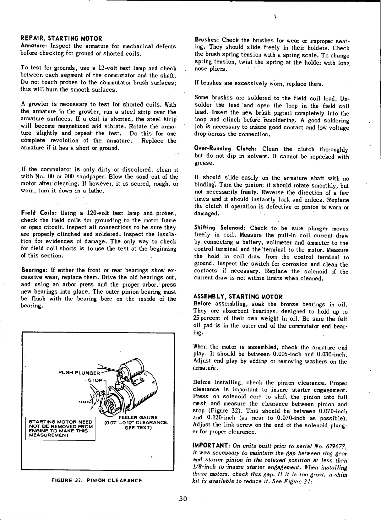
PUSH
PLUNGER
STOP
STARTING
MOTOR
NEED
NOT
BE
REMOVED
FROM
ENGINE
TO
MAKE
THIS
MEASUREMENT
FEELER
GAUGE
(0.07"-0.12"
CLEARANCE.
SEE
TEXT)
FIGURE
32.
PINION
CLEARANCE
Brushes: Check the
brushes
for wear or improper
seat-
ing.
They should slide freely in their holders. Check
the brush spring tension
with
a spring
scale.
To
change
spring
tension,
twist
the spring at the holder
with
long
nose
pliers.
If
brushes
are excessively
worn,
replace them.
Some
brushes
are soldered to the
field
coil
lead. Un-
solder thie lead and open the loop in the
field
coil
lead. Insert the new brush
pigtail
completely into the
loop
and
clinch
before" resoldering. A good soldering
job
is
necessary
to insure good contact and low voltage
drop
across
the connection.
Over-Running
Clutch: Clean the clutch thoroughly
but do not dip in solvent. It cannot be repacked
with
grease.
It
should slide easily on the armature shaft
with
no
binding.
Turn the
pinion;
it should rotate smoothly, but
not necessarily freely.
Reverse
the direction of a few
times and it should instantly lock and unlock.
Replace
the clutch if operation is defective or
pinion
is
worn
or
damaged.
Shifting
Solenoid: Check to be
sure
plunger moves
freely
in
coil.
Measure the
pull-in
coil
current draw
by
connecting a battery, voltmeter and ammeter to the
control
terminal and the terminal to the motor. Measure
the
hold
in
coil
draw
from
the control terminal to
ground.
Inspect the switch for corrosion and clean the
contacts
if
necessary.
Replace
the solenoid if the
current draw is not
within
limits
when cleaned.
ASSEMBLY,
STARTING
MOTOR
Before assembling,
soak
the bronze bearings in oil.
They are
absorbent
bearings, designed to
hold
up to
25
percent of their own weight in oil. Be
sure
the
felt
oil
pad is in the outer end of the commutator end
bear-
ing.
When
the. motor is
assembled,
check the armature end
play.
It should be between 0.005-inch and 0.030-inch.
Adjust
end play by adding or removing
washers
on the
armature.
Before installing, check the
pinion
clearance.
Proper
clearance
is important to insure
starter
engagement.
Press
on solenoid core to shift the
pinion
into
full
mesh and
measure
the
clearance
between
pinion
and
stop (Figure 32). This should be between 0.070-inch
and 0.120-inch (as
near
to 0.070-inch as possible).
Adjust
the
link
screw on the end of the solenoid plung-
er for proper
clearance.
IMPORTANT:
On
units built prior
to
serial
No.
679677,
it
was
necessary
to
maintain
the gap
between ring gear
and
starter pinion
in the
relaxed position
at
less than
1/8-inch
to
insure starter engagement. When installing
these motors, check this
gap. If it is too
great,
a
shim
kit
is
available
to
reduce
it. See
Figure
31.
30
 Loading...


