3. Touch red meter lead to
yellow
wire
plug
terminal
and other meter lead to metal core
of
.stator. If
meter doesn't read
infinity,
the stator
winding
is
grounded. Replace the stator.
Flywheel
Magnet
Group
or
Rotor
To
test the magnet group or rotor, lay a piece of ferrous
(iron)
material up against the magnets to be
sure
they
are changed. If not, replace the rotor. ...
MODELS
PRIOR
TO
SPEC
T
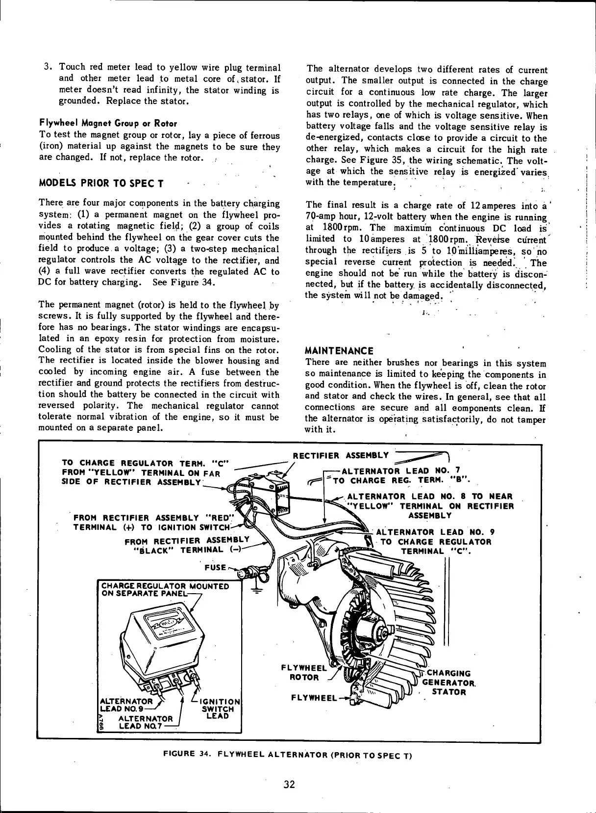
There are
four
major components in the battery charging
system: (1) a permanent magnet on the
flywheel
pro-
vides a rotating magnetic
field;
(2) a group of coils
mounted
behind the
flywheel
on thie
gear
cover cuts the
field
to produce a voltage; (3) a two-step mechanical
regulator
controls the AC voltage to the
rectifier,
and
(4)
a
full
wave
rectifier
converts the regulated AC to
DC
for battery charging. See Figure 34.
The permanent magnet
(rotor)
is held to the
flywheel
by
screws. It is
fully
supported by the
flywheel
and there-
fore
has no bearings. The stator windings are encapsu-
lated
in an epoxy resin for protection
from
moisture.
Cooling
of the stator is
from
special
fins
on the rotor.
The
rectifier
is located inside the blower housing and
cooled
by incoming engine air. A fuse between the
rectifier
and ground protects the rectifiers
from
destruc-
tion
should the battery be connected in the
circuit
with
reversed
polarity.
The mechanical regulator cannot
tolerate normal
vibration
of the engine, so it must be
mounted
on a
separate
panel.
The alternator develops two different
rates
of current
output.
The smaller output is connected in the charge
circuit
for a continuous low rate charge. The larger
output
is controlled by the mechanical regulator,
which
has two relays, one of
which
is voltage sensitive. When
battery voltage
falls
and the voltage sensitive relay is
de-energized, contacts close to provide a
circuit
to the
other relay,
which
makes a
circuit
for the
high
rate
charge. See Figure 35, the
wiring
schematic. The
volt-
age at
which
the sensitive relay is energized'varies,
with
the temperature.
The
final
result is a charge rate of
12
amperes
into
a'
70-amp hour,
12-volt
battery when the engine is running
at ISOOrpm. The maximum continuous DC load is
limited
to lOamperes at ISOOrpm. Reverse current
through
the rectifiers is 5 to lO'miiiiamperes, so no
special reverse current protection is needed. The
engine should not be' run
while
the battery is discon-
nected, but if the battery is accidentally disconnected,
the system
will
not be damaged.
1:
' ' . .
MAINTENANCE
There are neither
brushes
nor bearings in this system
so maintenance is
limited
to keeping the components in
good
condition.
When the
flywheel
is
off,
clean the rotor
and stator and check the wires. In general, see that all
connections are
secure
and all components clean. If
the alternator is operating satisfactorily, do not tamper
with
it.
TO CHARGE REGULATOR TERM.
"C"
FROM
"YELLOW"
TERMINAL
ON FAR
SIDE
OF
RECTIFIER ASSEMBLY
FROM
RECTIFIER ASSEMBLY
"RED
TERMINAL
(4-) TO
IGNITION
SWITCH
RECTIFIER
ASSEMBLY
FROM
RECTIFIER ASSEMBLY
"BLACK"
TERMINAL
(-)
ALTERNATOR LEAD
NO. 7
TO CHARGE
REG.
TERM.
"B".
ALTERNATOR LEAD
NO. 8 TO
NEAR
YELLOW"
TERMINAL
ON
RECTIFIER
ASSEMBLY
^ALTERNATOR LEAD
NO. 9
\\
TO
CHARGE REGULATOR
~-
TERMINAL
"C".
CHARGE REGULATOR
MOUNTED
ON SEPARATE PANEL-
ALTERNATOR
LEAD
NO.9-
^ ALTERNATOR
LEAD
NQ7 :
CHARGING
GENERATOR.
STATOR
IGNITION
SWITCH
LEAD
FIGURE
34.
FLYWHEEL ALTERNATOR
(PRIOR
TO
SPEC
T)
32
 Loading...


