IGNITION
SWITCH
RECTIFIER
YELLOW
__Y BLACK
20 AMP
FUSE
AND
FUSE
HOLDER
(Note:
Early
models
riot
equipped
with
fuse.)
12 V.
BATTERY
CHARGE
REGULATOR
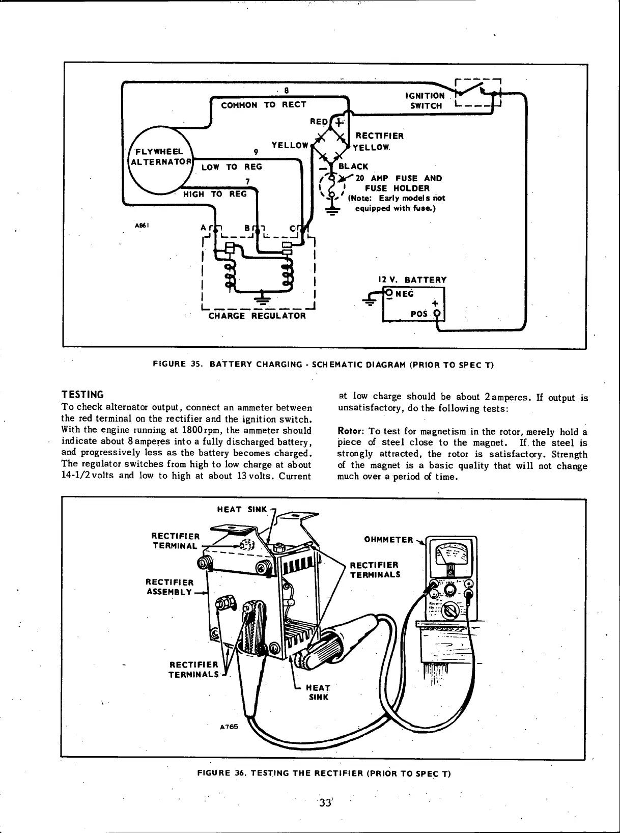
FIGURE 35. BATTERY CHARGING - SCHEMATIC DIAGRAM (PRIOR TO SPEC T)
TESTING
To check alternator output, connect an ammeter between
the red terminal on the rectifier and the ignition switch.
With the engine running at ISOOrpm, the ammeter should
indicate about 8 amperes into a fully discharged battery,
and progressively less as the battery becomes charged.
The regulator switches from high to low charge at about
14-1/2 volts and low to high at about 13 volts. Current
at low charge should be about 2amperes. If output is
unsatisfactory, do the following tests:
Rotor: To test for magnetism in the rotor, merely hold a
piece of steel close to the magnet. If the steel is
strongly attracted, the rotor is satisfactory. Strength
of the magnet is a basic quality that will not change
much over a period of time.
HEAT
SINK
RECTIFIER
TERMINAL
RECTIFIER
ASSEMBLY—*
RECTIFIER
TERMINALS
FIGURE 36. TESTING THE RECTIFIER (PRIOR TO SPEC T)
33'
 Loading...


