Compression of a standard new engine
prior
to
Spec
P
at about 300rpm is approximately 300 - 350psi.
Begin-
ning
Spec
P, compression is about 350 - 400 psi.
Compression reading
will
deviate considerably
from
the
above readings
because
of differences in cranking
speed,
altitude and ambient temperature conditions.
Therefore the specification is given
only
as a guide.
The
best
indication
of leakage is a compression in-
crease
when oil is added to the cylinder.
Disassembly:
1.
Remove the decompression solenoid.
2.
Remove the rocker box cover,
fuel
nozzle and
connecting
oil lines to the cylinder head.
3. Remove the intake and exhaust
manifold.
4.
Remove the cap screws
holding
the cylinder head
to
the cylinder block .
5. Remove the head. If it sticks, rap it sharply
with
a soft hammer. Do not use a pry.
6. Remove the rocker arms and push rods.
7. Using a valve spring compressor, disassemble the
valve
assemblies.
Repair:
Thoroughly
clean all components of the cylinder head
assembly. Remove all the carbon deposits
from
the
intake
and exhaust ports and clean all gasket surfaces.
Valves:
Remove all carbon and check each valve for
burning,
pitting,
or warped stem. Valves that are
slightly
pitted
or burned,
refinish
on an accurate valve
grinder.
Refinish intake valves to a 42-degree angle
and exhaust valves to a 45-degree angle. But, if they
are badly
pitted,
or
will
have a
thin
edge
when refacing,
replace them.
Check refinished valves for a
tight
seat
to the valve
seat
with
an air
pressure
type testing
tool
or by apply-
ing
Prussian Blue on the valve face and rotating it
against the
seat.
Valve
Guides: Check valve guide to valve clearance,
see Dimensions and Clearances Section. If the proper
clearances
cannot be obtained by replacing the valves,
replace the valve guides.
Drive
the old valve guides
into
the valve chambers.
Drive
new guides in
until
they protrude 11/32-inch
from
the rocker box side of
the head. Ream the new valve guide to obtain the pro-
per clearance.
Valve
Seats:
If the valve
seats
are
pitted,
refinish
them..
Using conventional
seat
grinding
equipment,
reface each
seat
to a 45-degree angle and a
seat
width
of
3/64 to 1/16-inch. You should be able to reface
each
seat
several times before it
becomes
necessary
to
replace it.
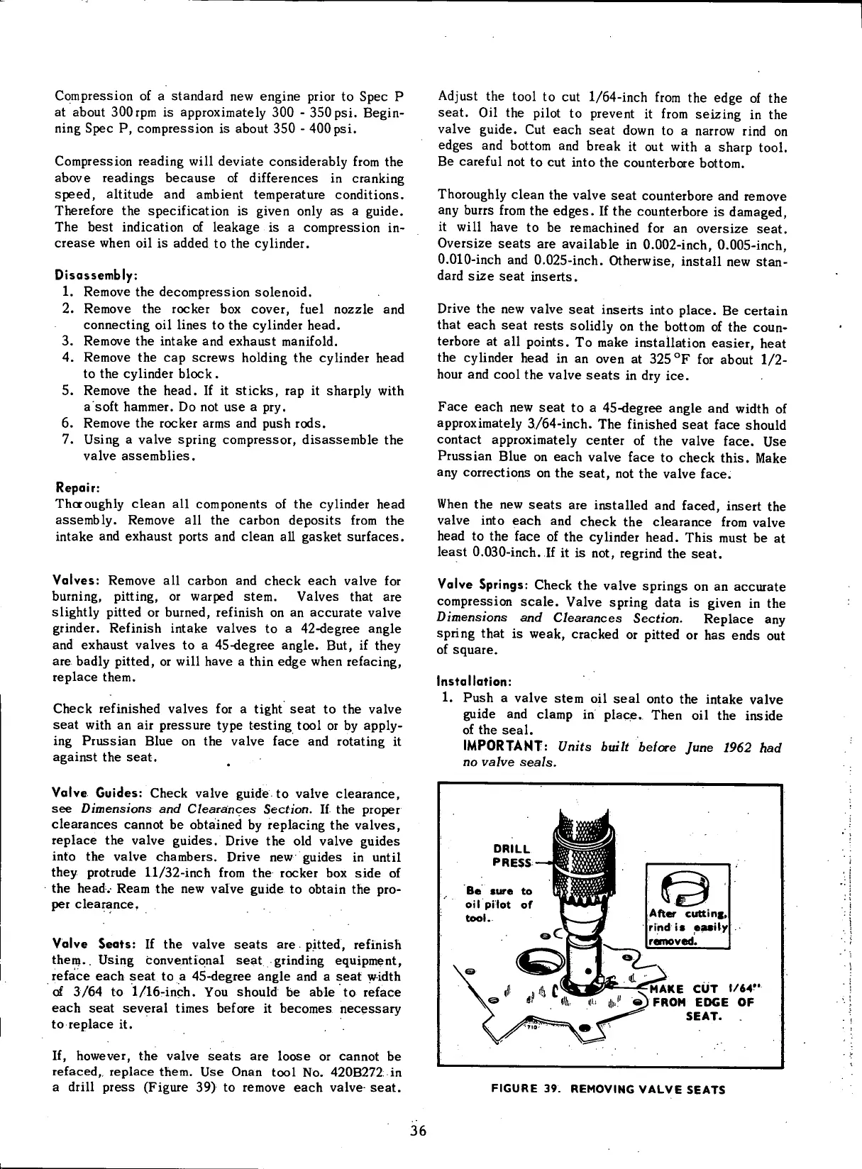
If,
however, the valve
seats
are loose or cannot be
refaced,, replace them. Use Onan
tool
No. 420B272 in
a
drill
press
(Figure 39) to remove each valve
seat.
Adjust
the
tool
to cut 1/64-inch
from
the
edge
of the
seat.
Oil the
pilot
to prevent it
from
seizing in the
valve
guide. Cut each
seat
down to a narrow
rind
on
edges
and bottom and break it out
with
a
sharp
tool.
Be
careful not to cut
into
the counterbore bottom.
Thoroughly
clean the valve
seat
counterbore and remove
any burrs
from
the
edges.
If the counterbore is damaged,
it will
have to be remachined for an oversize
seat.
Oversize
seats
are available in 0.002-inch, 0.005-inch,
0.
010-inch
and 0.025-inch. Otherwise,
install
new stan-
dard
size
seat
inserts.
Drive
the new valve
seat
inserts
into
place. Be certain
that each
seat
rests
solidly
on the bottom of the coun-
terbore at all points. To make installation
easier,
heat
the cylinder head in an oven at 325
0
F for about 1/2-
hour and
cool
the valve
seats
in dry ice.
Face
each new
seat
to a 45-degree angle and
width
of
approximately
3/64-inch. The finished
seat
face should
contact approximately center of the valve face. Use
Prussian Blue on each valve face to check this. Make
any corrections on the
seat,
not the valve face.
When
the new
seats
are installed and faced, insert the
valve
into
each and check the clearance
from
valve
head to the face of the cylinder head. This must be at
least 0.030-inch. If it is not, regrind the
seat.
Valve
Springs: Check the valve springs on an accurate
compression scale.
Valve
spring data is given in the
Dimensions
and Clearances Section. Replace any
spring
that is weak, cracked or
pitted
or has
ends
out
of
square.
Installation:
1.
Push a valve stem oil seal onto the intake valve
guide and clamp in place. Then oil the inside
of
the seal.
IMPORTANT: Units built before June
1962 had
no
valve seals.
DRILL
PRESS
Be
sure
to
oil
pilot
of
tool..
After
cutting,
rind
is easily
removed.
MAKE
CUT
1/64?'
FROM
EDGE
OF
SEAT.
FIGURE
39.
REMOVING
VALVE
SEATS
36
 Loading...


