2.
Oil the stem of each valve
lightly
and insert each
in
its own guide.
3. Check each valve for a
tight
seat
with
an air
pressure
type
tester.
If a
tester
is not available,
make pencil marks at intervals on the valve face
and observe if the marks rub off
uniformly
when
the valve is rotated part of a
turn
in the
seat.
If
the
seat
is not
tight,
regrind the valves.
4.
Using a valve spring compressor, compress each
valve
spring and insert the valve spring retainer,
and retainer locks.
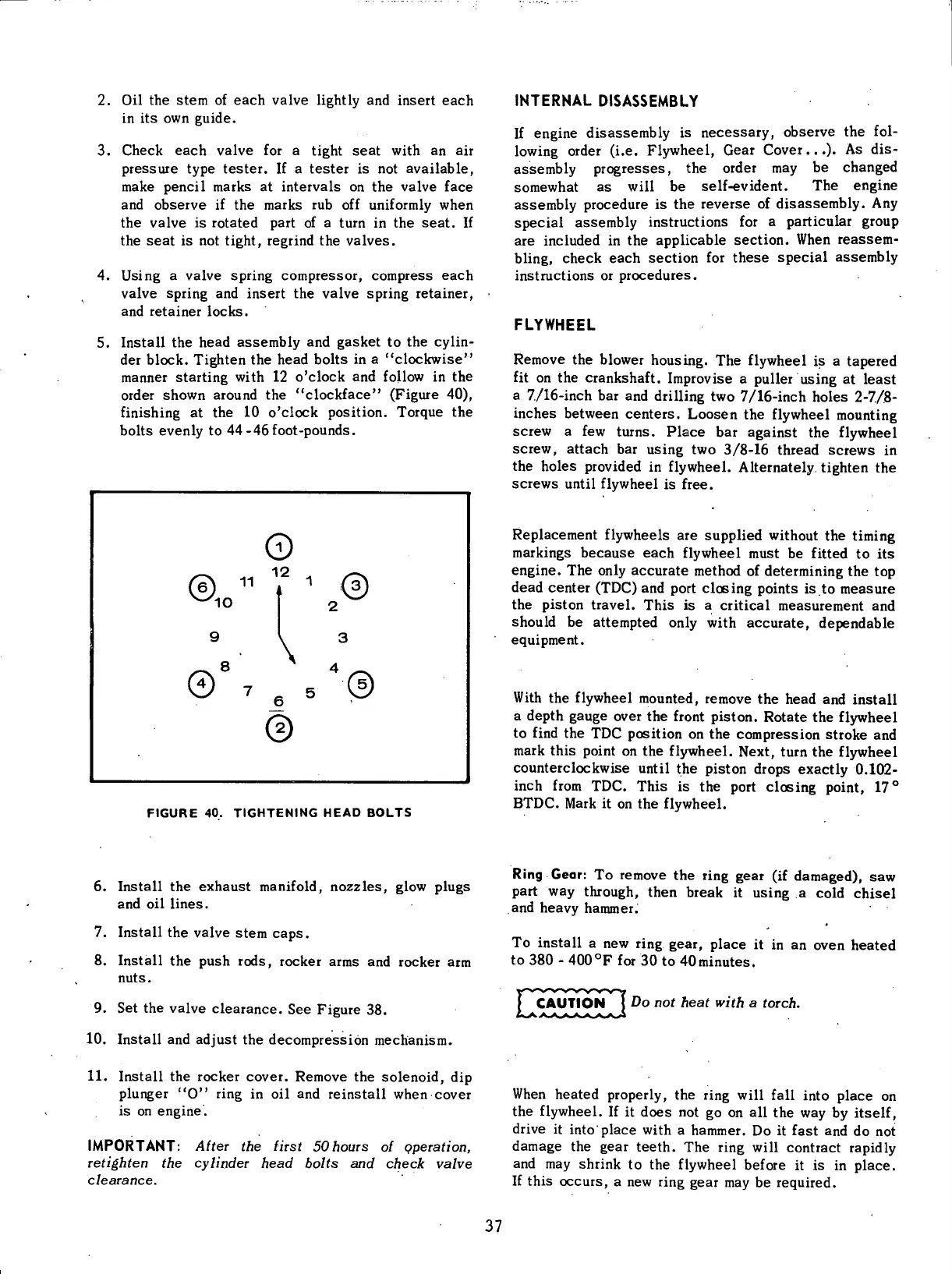
5.
Install
the head assembly and gasket to the
cylin-
der block. Tighten the head bolts in a "clockwise"
manner starting
with
12 o'clock and
follow
in the
order shown around the "clockface" (Figure 40),
finishing
at the 10 o'clock position. Torque the
bolts
evenly to 44-46foot-pounds.
FIGURE
40.
TIGHTENING
HEAD
BOLTS
INTERNAL
DISASSEMBLY
If
engine disassembly is
necessary,
observe the
fol-
lowing
order (i.e.
Flywheel,
Gear Cover...). As dis-
assembly
progresses,
the order may be changed
somewhat as
will
be self-evident. The engine
assembly procedure is the reverse of disassembly. Any
special assembly instructions for a particular group
are included in the applicable section. When
reassem-
bling,
check each section for
these
special assembly
instructions
or procedures.
FLYWHEEL
Remove the blower housing. The
flywheel
is a tapered
fit
on the crankshaft. Improvise a puller using at least
a 7./16-inch bar and
drilling
two 7/16-inch holes 2-7/8-
inches between centers. Loosen the
flywheel
mounting
screw a few turns. Place bar against the
flywheel
screw, attach bar using two 3/8-16 thread screws in
the holes provided in
flywheel.
Alternately tighten the
screws
until
flywheel
is free.
Replacement flywheels are supplied
without
the
timing
markings
because
each
flywheel
must be
fitted
to its
engine. The
only
accurate method of determining the top
dead center
(TDC)
and port closing points is.to
measure
the piston
travel.
This is a
critical
measurement and
should
be attempted
only
with
accurate, dependable
equipment.
With
the
flywheel
mounted, remove the head and
install
a depth
gauge
over the
front
piston. Rotate the
flywheel
to
find
the TDC position on the compression stroke and
mark
this point on the
flywheel.
Next,
turn
the
flywheel
counterclockwise
until
the piston drops exactly 0.102-
inch
from
TDC. This is the port closing point, 17°
BTDC.
Mark
it on the
flywheel.
6.
Install
the exhaust
manifold,
nozzles,
glow
plugs
and oil lines.
7.
Install
the valve stem
caps.
8.
Install
the push rods, rocker arms and rocker arm
nuts.
9. Set the valve clearance. See Figure 38.
10.
Install
and adjust the decompression mechanism.
11.
Install
the rocker cover. Remove the solenoid, dip
plunger
"O"
ring
in oil and reinstall when cover
is
on engine.
IMPORTANT: Alter
the
first SOhours
ol
operation,
retighten
the
cylinder head bolts
and
check valve
clearance.
Ring
Gear: To remove the
ring
gear
(if damaged), saw
part way through, then break it using a
cold
chisel
and heavy hammer.
To
install
a new
ring
gear,
place it in an oven heated
to
380 - 400
0
F for 30 to 40minutes.
j^CAUTION
Do
not
heat with
a
torch.
When
heated properly, the
ring
will
fall
into
place on
the
flywheel.
If it
does
not go on all the way by
itself,
drive
it
into
place
with
a hammer. Do it fast and do not
damage
the
gear
teeth. The
ring
will
contract
rapidly
and may shrink to the
flywheel
before it is in place.
If
this occurs, a new
ring
gear
may be required.
37
 Loading...


