GOVERNOR
CUP
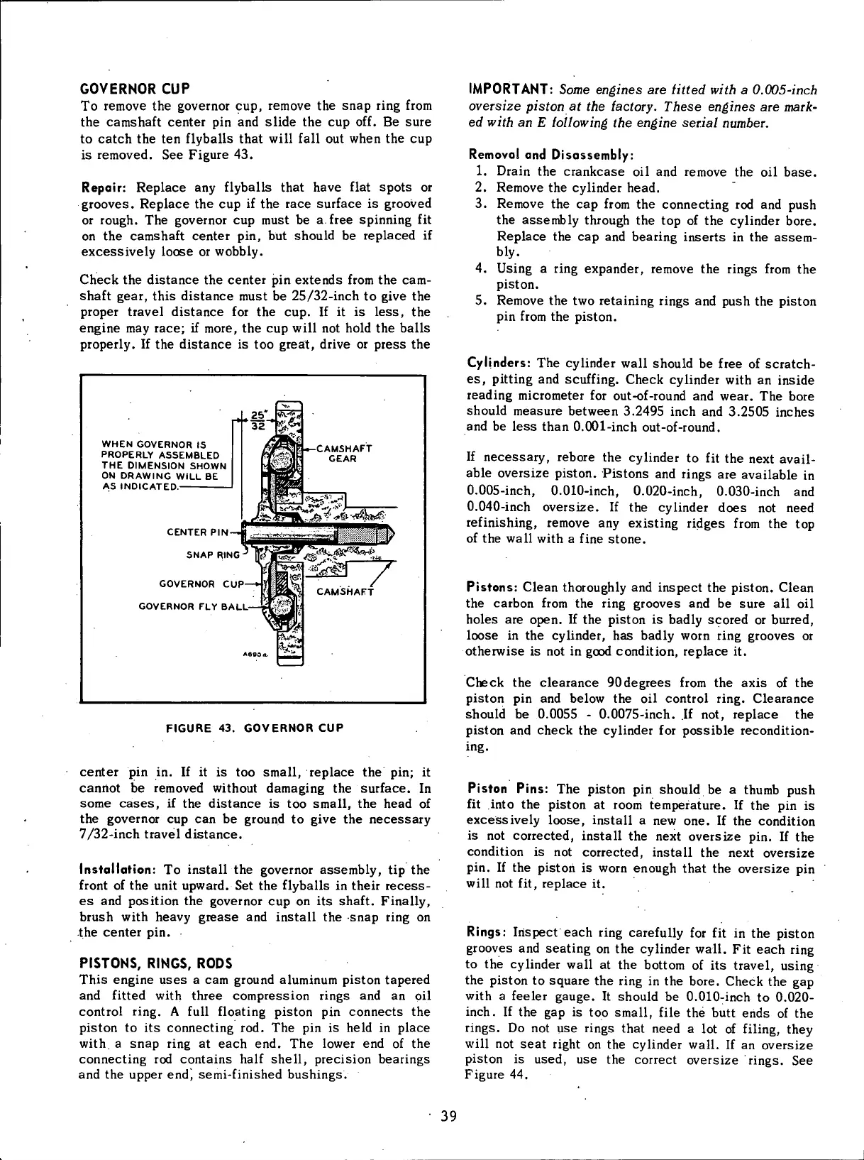
To
remove the governor cup, remove the
snap
ring
from
the camshaft center pin and slide the cup off. Be
sure
to
catch the ten
flyballs
that
will
fall
out when the cup
is
removed. See Figure 43.
Repair: Replace any
flyballs
that have
flat
spots
or
grooves. Replace the cup if the
race
surface is grooved
or
rough. The governor cup must be a.
free
spinning fit
on
the camshaft center pin, but should be replaced if
excessively loose or
wobbly.
Check the distance the center pin extends
from
the cam-
shaft
gear,
this distance must be 25/32-inch to give the
proper travel distance for the cup. If it is
less,
the
engine may race; if more, the cup
will
not
hold
the balls
properly.
If the distance is too great, drive or
press
the
IMPORTANT: Some engines
are
fitted with
a
0.005-inch
oversize piston
at the
factory. These engines
are
mark-
ed
with
an E
following
the
engine serial number.
WHEN
GOVERNOR
IS
PROPERLY
ASSEMBLED
THE
DIMENSION
SHOWN
ON
DRAWING
WILL
BE
AS
INDICATED.
CENTER
PIN
SNAP
RING
GOVERNOR
CUP—•
GOVERNOR
FLY
BALL
FIGURE
43. GOVERNOR CUP
center pin in. If it is too small, replace the pin; it
cannot be removed
without
damaging the surface. In
some
cases,
if the distance is too small, the head of
the governor cup can be ground to give the
necessary
7/32-inch
travel distance.
Installation:
To
install
the governor assembly, tip the
front
of the
unit
upward. Set the
flyballs
in their
recess-
es and position the governor cup on its shaft.
Finally,
brush
with
heavy
grease
and
install
the
snap
ring
on
the center pin.
PISTONS,
RINGS,
RODS
This
engine
uses
a cam ground aluminum piston tapered
and
fitted
with
three compression rings and an oil
control
ring.
A
full
floating
piston pin connects the
piston
to its connecting rod. The pin is held in place
with,
a
snap
ring
at each end. The lower end of the
connecting
rod contains
half
shell, precision bearings
and the upper end', semi-finished bushings.
Removal and Disassembly:
1.
Drain
the crankcase oil and remove the oil
base.
Remove the cylinder head.
Remove the cap
from
the connecting rod and push
the assembly through the top of the cylinder bore.
Replace the cap and bearing inserts in the
assem-
bly.
Using
a
ring
expander, remove the rings
from
the
piston.
Remove the two retaining rings and push the piston
pin
from
the piston.
2.
3.
4.
5.
Cylinders:
The cylinder
wall
should be free of scratch-
es,
pitting
and
scuffing.
Check cylinder
with
an inside
reading micrometer for out-of-round and wear. The bore
should
measure
between 3.2495
inch
and 3.2505 inches
and be
less
than 0.001-inch out-of-round.
If
necessary,
rebore the cylinder to
fit
the next
avail-
able oversize piston. Pistons and rings are available in
0.005-inch,
0.010-inch, 0.020-inch, 0.030-inch and
0.040-inch
oversize. If the cylinder
does
not need
refinishing,
remove any existing ridges
from
the top
of
the
wall
with
a
fine
stone.
Pistons: Clean thoroughly and inspect the piston. Clean
the carbon
from
the
ring
grooves and be
sure
all oil
holes are open. If the piston is badly scored or burred,
loose in the cylinder, has badly
worn
ring
grooves or
otherwise is not in good
condition,
replace it.
Check the clearance
90degrees
from
the axis of the
piston
pin and below the oil
control
ring.
Clearance
should
be 0.0055 - 0.0075-inch. If not, replace the
piston
and check the cylinder for possible recondition-
ing.
Piston
Pins: The piston pin should be a thumb push
fit
into
the piston at room temperature. If the pin is
excessively loose,
install
a new one. If the
condition
is
not corrected,
install
the next oversize pin. If the
condition
is not corrected,
install
the next oversize
pin.
If the piston is
worn
enough that the oversize pin
will
not
fit,
replace it.
Rings:
Inspect each
ring
carefully for fit in the piston
grooves and seating on the cylinder
wall.
Fit each
ring
to
the cylinder
wall
at the bottom of its
travel,
using
the piston to
square
the
ring
in the bore. Check the gap
with
a feeler gauge. It should be 0.010-inch to 0.020-
inch.
If the gap is too small,
file
the butt
ends
of the
rings.
Do not use rings that need a lot of
filing,
they
will
not
seat
right
on the cylinder
wall.
If an oversize
piston
is used, use the correct oversize rings. See
Figure
44.
'
39
 Loading...


