A859
II
HEAVIEST
COMPRESSION
RING
IN TOP
GROOVE
COMPRESSION
RINGS
r-OIL
CONTROL
RING
-i
RAIL
-RAIL
"EXPANDER
CONNECTING
ROD
BUSHINGS—
BUSHING
ENDS
MUST
BE
FLUSH
WITH
SIDES
OF
ROD TO
PERMIT
1/16"
OIL
GROOVE
BETWEEN
BUSHINGS
PRECISION
TYPE
BEARING
CROSS-SECTION
MEASURE
CLEARANCE
IN
DIRECTION
INDICATED
BY
ARROW
A88I
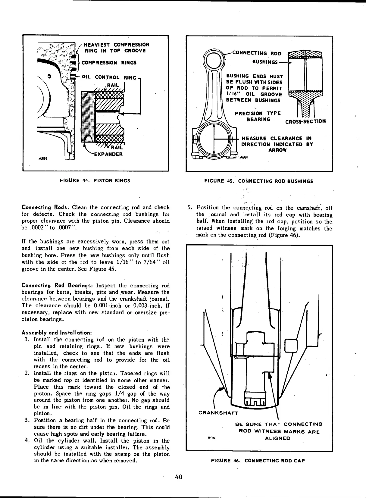
FIGURE
44.
PISTON
RINGS
FIGURE
45.
CONNECTING
ROD
BUSHINGS
Connecting Rods: Clean the connecting rod and check
for
defects. Check the connecting rod bushings for
proper
clearance
with
the piston pin.
Clearance
should
be .0002"to .0007".
If
the bushings are excessively
worn,
press
them out
and install one new bushing
from
each
side of the
bushing bore.
Press
the new bushings only
until
flush
with
the side of the rod to leave 1/16" to 7/64" oil
groove in the
center.
See Figure 45.
Connecting Rod Bearings: Inspect the connecting rod
bearings for burrs, breaks, pits and wear. Measure the
clearance
between bearings and the crankshaft journal.
The
clearance
should be 0.001-inch or 0.003-inch. If
necessary,
replace
with
new standard or oversize pre-
cision
bearings.
Assembly
and
Installation:
1.
Install the connecting rod on the piston
with
the
pin
and retaining rings. If new bushings were
installed,
check to see that the
ends
are flush
with
the connecting rod to provide for the oil
recess
in the
center.
2.
Install the rings on the piston. Tapered rings
will
be marked top or identified in
some
other manner.
Place
this mark toward the closed end of the
piston.
Space
the
ring
gaps
1/4 gap of the way
around the piston
from
one
another.
No gap should
be in
line'
with
the piston pin. Oil the rings and
piston.
3. Position a bearing
half
in the connecting rod. Be
sure
there
is no
dirt
under the bearing. This could
cause
high
spots
and early bearing failure.
4.
Oil the cylinder
wall.
Install the piston in the
cylinder
using a suitable installer. The assembly
should be installed
with
the
stamp
on the piston
in
the
same
direction as when removed.
5. Position the connecting rod on the camshaft, oil
the journal and install its rod cap
with
bearing
half.
When installing the rod cap, position so the
raised witness mark on the
forging
matches
the
mark on the connecting rod (Figure 46).
CRANKSHAFT
BE
SURE
THAT
CONNECTING
ROD
WITNESS
MARKS
ARE
ALIGNED
FIGURE
46.
CONNECTING
ROD CAP
40
 Loading...


