CRANKSHAFT
GEAR^
GEAR
PULLER
^^GEAR
jr/PULLER
AIRING
s#
Jf
^We^V
/ ./
FIG.
13-7
the crankshaft
gear.
2. Pull
off the crankshaft
gear.
It has 2-1/4-20 UNC
tapped holes for attaching a
gear
pulling ring.
Use
care
not
to
damage
teeth if the
gear
is to be re-used.
3. Remove the oil pan, piston, and connecting rod.
4.
Remove the
rear
bearing plate
from
the
crankcase.
5. Remove the crankshaft through the
rear
opening
in
the
crankcase.
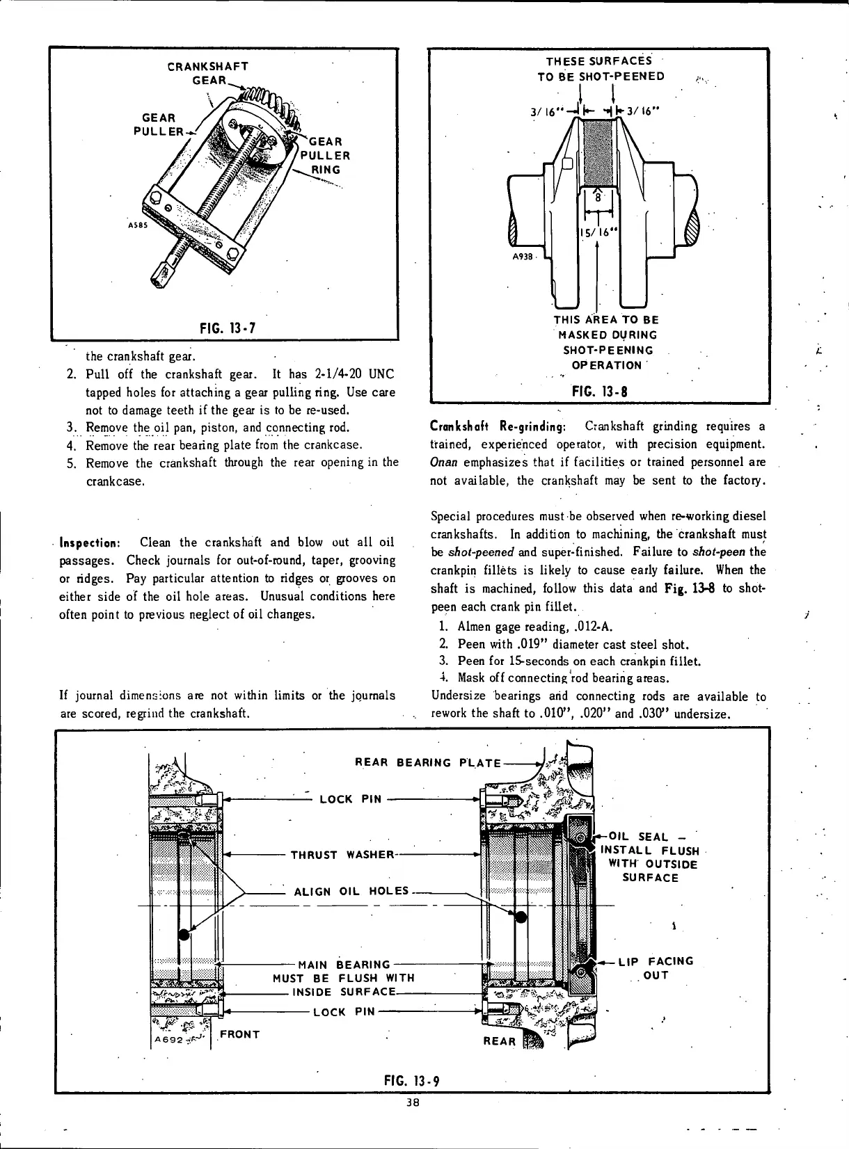
THESE SURFACES
TO
BE
SHOT-PEENED
I
1
3/l6"-Jk
Hka/U"
THIS AREA
TO BE
MASKED DURING
SHOT-PEENING
OPERATION
FIG.
13-8
Crankshaft Re-grinding: Crankshaft grinding requires a
trained,
experienced operator,
with
precision equipment.
Onan
emphasizes
that if
facilities
or trained personnel are
not
available, the crankshaft may be
sent
to the factory.
Inspection:
Clean the crankshaft and
blow
out all oil
passages.
Check journals for
out-of-round,
taper,
grooving
or
ridges. Pay particular attention to ridges or grooves on
either side of the oil hole
areas.
Unusual conditions
here
often
point to previous neglect of
oil
changes.
If
journal dimensions are not
within limits
or the journals
are scored, regrind the crankshaft.
Special procedures must be observed when
re-working
diesel
crankshafts. In addition to machining, the crankshaft must
be
shot-peened
and super-finished. Failure to shot-peen the
crankpin
fillets
is
likely
to
cause
early
failure.
When the
shaft is machined,
follow
this
data
and Fig. 13-8 to shot-
peen
each
crank pin
fillet.
1.
Almen
gage
reading, .012-A.
2.
Peen
with
.019" diameter
cast
steel shot.
3.
Peen
for
15-seconds
on
each
crankpin
fillet.
4.
Mask
off
connecting rod bearing
areas.
Undersize bearings
arid
connecting rods are available to
rework
the shaft to .010", .020" and .030" undersize.
REAR BEARING PLATE
LOCK
PIN
THRUST WASHER
ALIGN
OIL
HOLES
MAIN BEARING
MUST
BE
FLUSH WITH
INSIDE SURFACE
LOCK
PIN
FRONT
OIL SEAL
-
INSTALL FLUSH
WITH OUTSIDE
SURFACE
LIP FACING
OUT
REAR
FIG.
13-9
38
 Loading...


