FUEL
TRANSFER
PUMP
The transfer pump is located on the left side of the
engine. If fuel does not reach the secondary filter,
make the following checks before removing the
pump.
1.
Check the fuel tank and see that the shutoff valve
is open.
2.
Remove the fuel line from the transfer pump
outlet and work the priming lever on the pump.
Fuel should spurt out of the pump. If not, remove
the pump for repair or replacement.
Testing
If the transfer pump delivers
fuel,
test it with a
pressure gauge or manometer. Perform these tests
before removing the pump from the engine. Remove
the pump outlet and install the pressure gauge. See
Figure 15.
Test the valves and diaphragm by operating the
primer lever a few times and watching the pressure. It
should not drop off rapidly after priming has stopped.
Next run the engine at governed speed on fuel
provided by gravity feed and measure the fuel pump
pressure developed. Pressure should be between 5
and 6 psi with the gauge 16 inches above the fuel
pump.
A low pressure reading indicates extreme wear in one
part or some wear
in
all parts, and the pump should be
overhauled or replaced. If the reading is above
maximum, the diaphragm is probably too tight or the
diaphragm spring too strong. This can also be caused
byfuel seeping underthediaphragm retainer nut and
between the diaphragm layers, causing a bulge in the
diaphragm. Overhaul the pump and replace the
defective parts. See Figure 16.
Low pressure with little or no pressure leak after
pumping stops indicates a weak or broken spring or
worn linkage and in most cases the pump should be
replaced.
Repair
Transfer pump failure is usually due to a leaking
diaphragm, valve or valve gasket. A kit is available for
replacement of various parts. Because the extent of
wear cannot be detected by the eye, replace all parts
in the kit. If the diaphragm is broken or leaks, check
for diluted crankcase oil and replace.
Occasionally, failureisduetoabrokenorweak spring
or wear in the linkage. In this case, replace the worn
parts or install a new pump. Obtain replacement parts
or install a new pump. Obtain replacement parts other
than the repair kit from an original equipment parts
distributor.
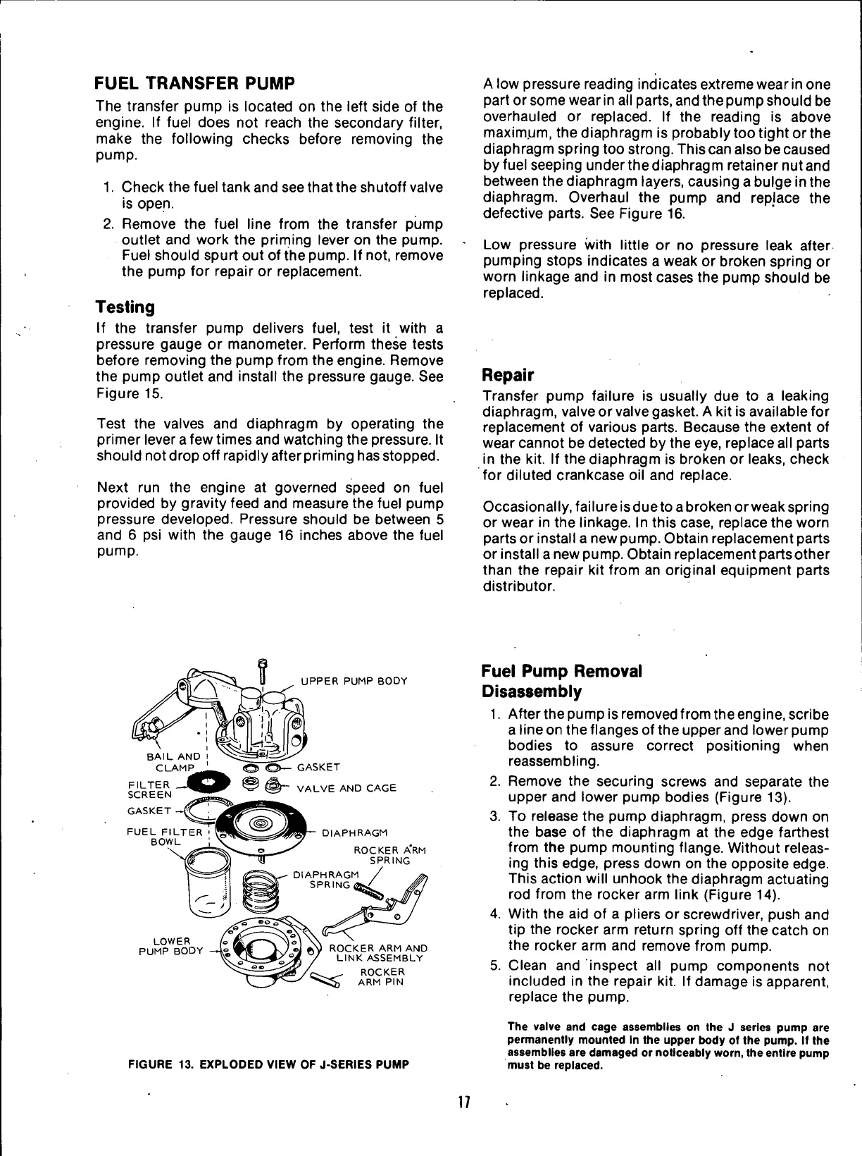
UPPER PUMP BODY
GASKET
VALVE AND CAGE
DIAPHRAGM
ROCKER ARM
SPRING
DIAPHRAGM
SPRING
LOWER
PUMP BODY
ftV ROCKER ARM AND
7
LINK ASSEMBLY
t „ ROCKER
>,
^$ ARM PIN
FIGURE 13. EXPLODED VIEW OF J-SERIES PUMP
Fuel
Pump Removal
Disassembly
1.
After the pump is removed from the eng
ine,
scribe
a line on the flanges of the upper and lower pump
bodies to assure correct positioning when
reassembling.
2.
Remove the securing screws and separate the
upper and lower pump bodies (Figure 13).
3. To release the pump diaphragm, press down on
the base of the diaphragm at the edge farthest
from the pump mounting flange. Without releas-
ing this edge, press down on the opposite edge.
This action will unhook the diaphragm actuating
rod from the rocker arm link (Figure 14).
4.
With the aid of a pliers or screwdriver, push and
tip the rocker arm return spring off the catch on
the rocker arm and remove from pump.
5. Clean and inspect all pump components not
included in the repair kit. If damage is apparent,
replace the pump.
The valve and cage assemblies on Ihe J series pump are
permanently mounted in the upper body of the pump. If the
assemblies are damaged or noticeably worn, theentire pump
must be replaced.
17
 Loading...


