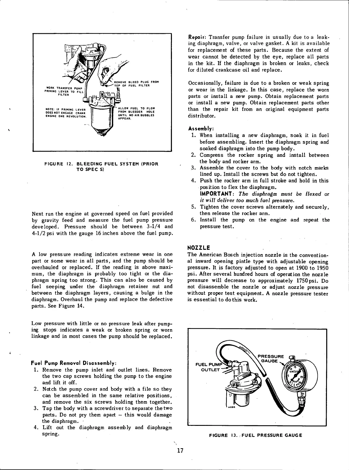
WORK
TRANSFER
PUMP
PRIMING
LEVER TO
FILL
FILTER
NOTE: IF
PRIMING
LEVER
DOES
NOT
ENGAGE
CRANK
ENGINE
ONE REVOLUTION
REMOVE
BLEED PLUG
FROM
TOP OF FUEL
FILTER
ALLOW
FUEL TO
FLOW
FROM
BLEEDER
HOLE
UNTIL
NO
AIR
BUBBLES
APPEAR.
FIGURE
12.
BLEEDING
FUEL
SYSTEM
(PRIOR
TO
SPEC
S)
Next
run the engine at governed
speed
on
fuel
provided
by
gravity feed and
measure
the
fuel
pump
pressure
developed.
Pressure
should be between 3-1/4 and
4-1/2 psi
with
the
gauge
16 inches above the
fuel
pump.
Repair: Transfer pump failure is usually due to a leak-
ing
diaphragm, valve, or valve
gasket.
A kit is available
for
replacement of
these
parts.
Because
the extent of
wear cannot be detected by the eye, replace all parts
in
the kit. If the diaphragm is broken or leaks, check
for
diluted
crankcase
oil and replace.
Occasionally,
failure is due to a broken or weak spring
or
wear in the linkage. In this
case,
replace the
worn
parts or
install
a new pump. Obtain replacement parts
or
install
a new pump. Obtain replacement parts other
than the repair kit
from
an
original
equipment parts
distributor.
Assembly:
1.
When
installing
a new diaphragm,
soak
it in
fuel
before assembling. Insert the diaphragm spring and
soaked diaphragm into the pump body.
2.
Compress the rocker spring and
install
between
the body and rocker arm.
3. Assemble the cover to the body
with
notch marks
lined
up.
Install
the screws but do not tighten.
4.
Push the rocker arm in
full
stroke and
hold
in this
position
to
flex
the diaphragm.
IMPORTANT:
The
diaphragm must
be
flexed
or
it
will deliver
too
much fuel pressure.
5. Tighten the cover screws alternately and securely,
then
release
the rocker arm.
6.
Install
the pump on the engine and
repeat
the
pressure
test.
A
low
pressure
reading indicates extreme wear in one
part or
some
wear in all parts, and the pump should be
overhauled or replaced. If the reading is above
maxi-
mum,
the diaphragm is probably too
tight
or the dia-
phragm spring too strong. This can also be
caused
by
fuel
seeping under the diaphragm retainer nut and
between the diaphragm layers, causing a bulge in the
diaphragm. Overhaul the pump and replace the defective
parts. See Figure 14.
NOZZLE
The American Bosch
injection
nozzle is the convention-
al
inward
opening pintle type
with
adjustable opening
pressure.
It is factory adjusted to open at 1900 to 1950
psi.
After
several hundred hours of operation the nozzle
pressure
will
decrease
to approximately
1750 psi.
Do
not
disassemble
the nozzle or adjust nozzle
pressure
without
proper
test
equipment. A nozzle
pressure
tester
is
essential to
do
this
work.
Low
pressure
with
little
or no
pressure
leak after pump-
ing
stops
indicates a weak or broken spring or
worn
linkage
and in most
cases
the pump should be replaced.
Fuel
Pump Removal Disassembly:
1.
Remove the pump
inlet
and outlet lines. Remove
the two cap screws holding the.
pump
to the engine
and
lift
it off.
2.
Notch the pump cover and body
with
a
file
so they
can be assembled in the
same
relative positions,
and remove the six screws holding them together.
3. Tap the body
with
a screwdriver to
separate
the
two
parts. Do not pry them apart
—
this
would
damage
the diaphragm. -
4. Lift
out the diaphragm assembly and diaphragm
spring.
FUEL
PUMP
OUTLET
FIGURE
13.
FUEL
PRESSURE
GAUGE
17
 Loading...


