Never
use hard or
sharp
tools, emery
paper,
grinding
powder or abrasives of any
kind.
Soak each nozzle in
fuel
to loosen
dirt.
Then clean the
inside
with
a small strip of
wood
soaked in oil and the
spray hole
with
a
wood
splinter. If
necessary,
clean the
outer surfaces of the nozzle body
with
a
brass
brush but
do not attempt to
scrape
carbon
from
the nozzle sur-
faces. This can severely
damage
the spray hole. Use a
soft
oil-soaked rag or mutton
tallow
and
felt
to clean
the nozzle valve.
Repair: If cleaning
will
not eliminate a nozzle defect,
replace the nozzle or take it to an authorized service
station.
Do not attempt to replace nozzle parts except
for
the nozzle and pintle assembly.
Assembly:
Rinse both the valve and nozzle thoroughly
before assembly and coat
with
oil. The valve must be
free in the nozzle.
Lift
it about 1/3 way out of the
body.
It should slide back to its
seat
without
aid when
the assembly is held at a
45°
angle. If
necessary,
work
the valve
into
its body
with
clean mutton
tallow.
1.
Remove all
pressure
on the nozzle spring by
adjusting
the
pressure
adjusting screw.
2.
Clamp the nozzle holder body in a vise.
3. Set the valve in the body and set the nozzle over
it.
4.
Install
the nozzle cap nut loosely.
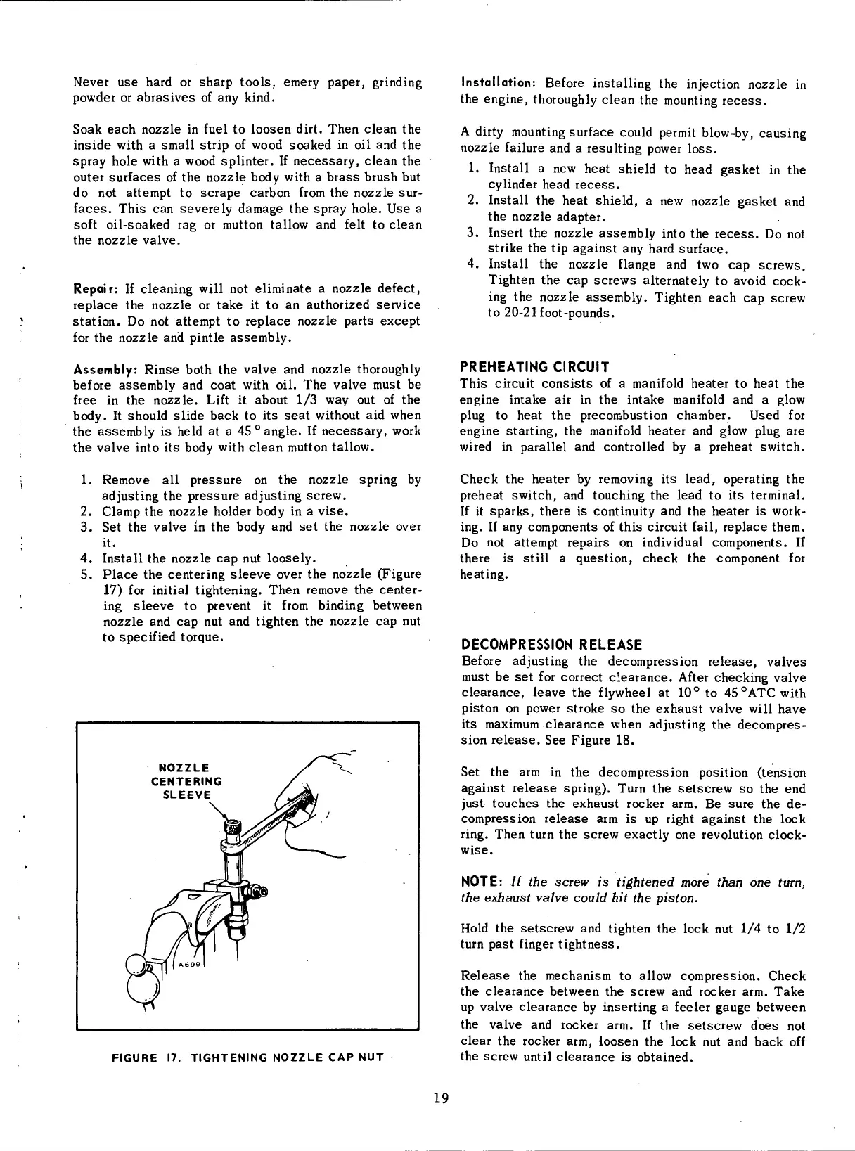
5. Place the centering sleeve over the nozzle (Figure
17)
for
initial
tightening. Then remove the center-
ing
sleeve to prevent it
from
binding
between
nozzle and cap nut and tighten the nozzle cap nut
to
specified torque.
NOZZLE
CENTERING
SLEEVE
FIGURE
17.
TIGHTENING
NOZZLE
CAP NUT
Installation:
Before
installing
the
injection
nozzle in
the engine, thoroughly clean the mounting
recess.
A
dirty
mounting
surface
could
permit
blow-by,
causing
nozzle
failure
and a resulting power loss.
1.
Install
a new
heat
shield to head gasket in the
cylinder
head
recess.
2.
Install
the
heat
shield, a new nozzle gasket and
the nozzle
adapter.
3. Insert the nozzle assembly
into
the
recess.
Do not
strike
the tip against any hard surface.
4.
Install
the nozzle flange and two cap screws.
Tighten
the cap screws alternately to
avoid
cock-
ing
the nozzle assembly. Tighten each cap screw
to 20-21
foot-pounds.
PREHEATING
CIRCUIT
This
circuit
consists of a
manifold
heater
to
heat
the
engine intake air in the intake
manifold
and a
glow
plug
to
heat
the precombustion chamber. Used for
engine starting, the
manifold
heater
and
glow
plug
are
wired
in parallel and controlled by a preheat
switch.
Check the
heater
by removing its lead, operating the
preheat
switch,
and touching the lead to its terminal.
If
it sparks, there is
continuity
and the
heater
is
work-
ing.
If any components of this
circuit
fail,
replace them.
Do
not attempt repairs on
individual
components. If
there is
still
a question, check the component for
heating.
DECOMPRESSION
RELEASE
Before
adjusting the decompression
release,
valves
must be set for correct clearance.
After
checking valve
clearance, leave the
flywheel
at 10° to
45
0
ATC
with
piston
on power stroke so the exhaust valve
will
have
its
maximum clearance when adjusting the decompres-
sion
release.
See Figure 18.
Set the arm in the decompression position (tension
against
release
spring).
Turn
the setscrew so the end
just
touches the exhaust rocker arm. Be
sure
the de-
compression
release
arm is up
right
against the
lock
ring.
Then
turn
the screw exactly one
revolution
clock-
wise.
NOTE:
// the
screw
is
tightened more than
one
turn,
the
exhaust valve could
hit the
piston.
Hold
the setscrew and tighten the
lock
nut 1/4 to 1/2
turn
past
finger tightness.
Release
the mechanism to
allow
compression. Check
the clearance between the screw and rocker arm. Take
up valve clearance by inserting a feeler
gauge
between
the valve and rocker arm. If the setscrew
does
not
clear the rocker arm, loosen the
lock
nut and back off
the screw
until
clearance is obtained.
19
 Loading...


