9-5
8. Connect a lifting hoist to the lifting eye on the
top of the endbell and slowly raise the genera-
tor end of the genset so the bottom of the end-
bell is higher than the side of the base assem-
bly. Place a wooden block under the stator
housing to support the genset. (Use the endbell
and engine lifting eye if the genset is to be
moved away from the base.) Remove the scroll
housing from the endbell.
Begin Spec B Instructions:
4. Remove the exhaust manifold to engine
mounting nuts. Remove the muffler to base
mounting screws and slide the muffler to the
right so the exhaust manifold pipe clears the
engine.
5. Remove the engine and generator to base
mounting bolts (4). (Apply antiseize lubricant to
the treads of these bolts before reinstallation.)
6. Disconnect the J4 and P1 harness connectors
at the air housing assembly. Remove the leads
from the start solenoid. Remove the control as-
sembly (A1) mounting bracket with the voltage
regulator, control assembly and start solenoid
attached. Disconnect the remaining harness
connections to the fuel pump, ground terminal
and load connections.
7. Carefully lift the generator end of the genset
and place a wooden block under the stator
housing to support the genset.
NOTE: For access to the air preheat door, re-
move the air housing assembly cover at this
point.
8. Remove the air housing assembly from the
endbell (Figure 9-2 on Page 9-4).
Spec A and Begin Spec B:
9. Secure the fan hub assembly and remove the
rotor through bolt and washer.
10. Remove the alignment key from the end of the
rotor shaft and save for reassembly. Remove
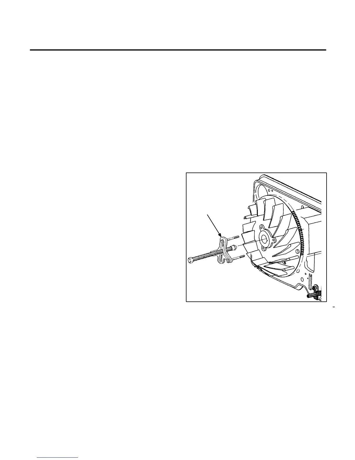
fan hub assembly with a wheel puller (Figure
9-3) Attach the wheel puller to the fan hub as-
sembly with three 5/16-inch thread tapping cap
screws (or tap fan hub with 3/8-inch tap and
use 3/8-inch cap screw).
M1904s
PULLER
FIGURE 9-3. PULLING THE FAN HUB ASSEMBLY
 Loading...

