10-4
VT1037-2s
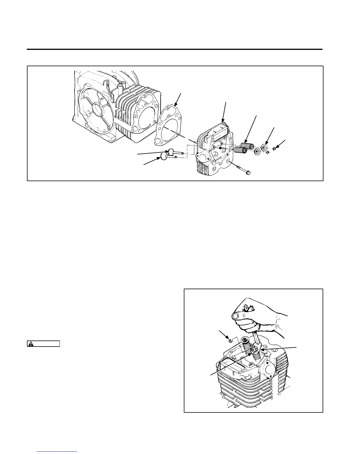
RETAINERS
CYLINDER
HEAD
EXHAUST
VALVE
VALVE
SPRINGS
GASKET
KEEPERS
INTAKE
VALVE
FIGURE 10-6. OVERHEAD VALVE SYSTEM
VALVE SYSTEM
This engine uses an overhead valve design, as
shown in Figure 10-6. A properly functioning valve
system is essential for good engine performance.
Access to the valve system is gained by removing
the head cover and cylinder head. Use the following
procedures to inspect and service the valve system.
Valve Removal
The intake and exhaust valves can be removed
from the cylinder head without the use of special
tools. Depress the valve spring retainer using a 9/16
inch crows foot on a 6 inch extension, then remove
the keeper (Figure 10-7). Remove the spring retain-
er, spring and valve.
WARNING
Always wear safety glasses with
side shields when removing springs to prevent
severe eye damage.
Inspection
Valve Face:
Check the valve face for evidence of
burning, warping, out-of-round, and carbon depos-
its (see Figure 10-8 on Page 10-5).
Burning and pitting are caused by the valve failing to
seat tightly. This condition is often caused by hard
carbon particles on the seat. It may also be due to
weak valve springs, insufficient tappet clearance,
warping, and misalignment.
Warping occurs mainly due to exposure to intense
heat. Out-of-round wear follows when the seat is
pounded by a valve whose head is not in line with
the stem and guide. If a valve face is burned or
warped, or the stem worn, install a new one.
VT1038-1s
KEEPER
9/16 INCH
CROWS
FOOT
RETAINER
FIGURE 10-7. VALVE REMOVAL
 Loading...

