8. Primary Engine Systems
8-1
INTRODUCTION
This section describes the engine primary systems
service procedures. Many of the primary systems
can be serviced without removing the genset from
the vehicle. Poor engine performance is often
caused by a dirty carburetor. Make certain that the
carburetor is clean before troubleshooting for per-
formance problems.
Primary engine systems include:
• Cooling system
• Exhaust system
• Ignition system
• Crankcase ventilation system
• Governor
• Fuel system
• Electric starter
COOLING SYSTEM
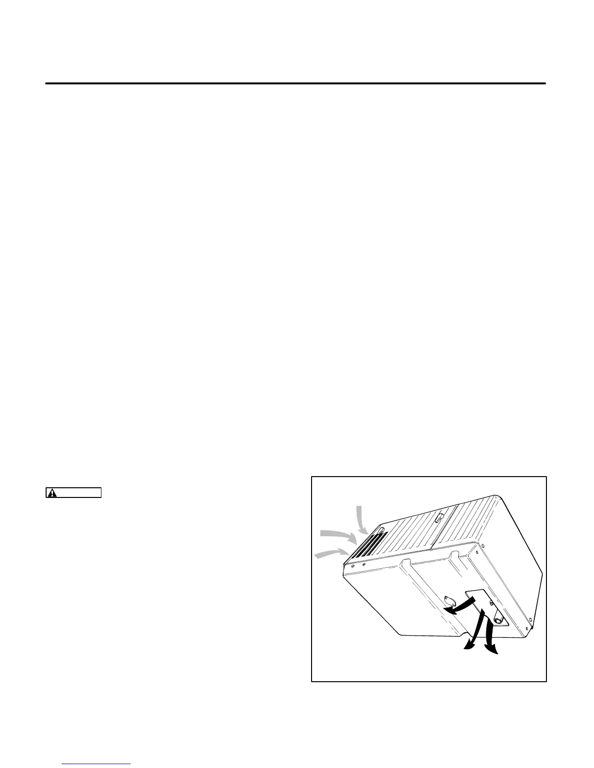
The genset requires a constant airflow to cool the
engine and generator during operation. A centrifu-
gal fan on the generator end of the genset provides
the required airflow. The fan draws cooling air
through the air inlet, into the generator and forces it
across the engine cooling fins. The air is discharged
through the air outlet. See Figure 8-1.
WARNING
Cooling air can contain poisonous
exhaust gases that can result in severe person-
al injury or death. Never use discharged cooling
air to heat the vehicle interior.
The air inlet is sized to allow the required flow rate of
cooling air. The air inlet opening and the air dis-
charge opening must be kept free of any obstruc-
tions to avoid restricting airflow. Dirt, dust, or other
debris that clog the air openings should be removed
during periodic maintenance. Dirt might also be-
come lodged between the cooling fins on the engine
block and cylinder head. If this happens, heat trans-
fer is greatly reduced and overheating can occur.
The cooling system consists of the genset housing
and base assembly enclosure, insulation duct,
scroll assembly, fan hub assembly, and air duct.
The following section covers service procedures for
the cooling system .
Inspection
Inspect the air inlet and outlet passages. Remove
the access panel and inspect the engine and control
area. If the engine is clean and the air inlet area is
clean, disassembly for engine cleaning will not be
necessary. If debris is visible, proceed to the
Disas-
sembly
section following.
Disassembly
Remove the genset as described in
Set Removal
Guidelines
on Page 5-2.
1. Follow the genset disassembly procedures in
Section
9. Generator
through the scroll assem-
bly removal.
2. Inspect and clean the fan hub assembly using
a brush or low pressure compressed air. If the
cooling fins are damaged, replace the fan hub
assembly as described in Section
9. Genera-
tor
.
3. Remove the top and bottom air guide housings
(cowling) to access the engine cooling fins for
cleaning.
4. Use a brush or low pressure compressed air to
remove any dirt or debris that may be lodged on
the engine cooling fins.
AIR
INLET
AIR
OUTLET
M1900-3s
FIGURE 8-1. COOLING AIRFLOW (SPEC B
SHOWN)
 Loading...

