7. Control
7-1
INTRODUCTION
This section covers control operation, component
locations, basic troubleshooting and test proce-
dures. The control consists of the circuitry used for
starting, monitoring fault conditions, instrumenta-
tion, battery charging, and stopping.
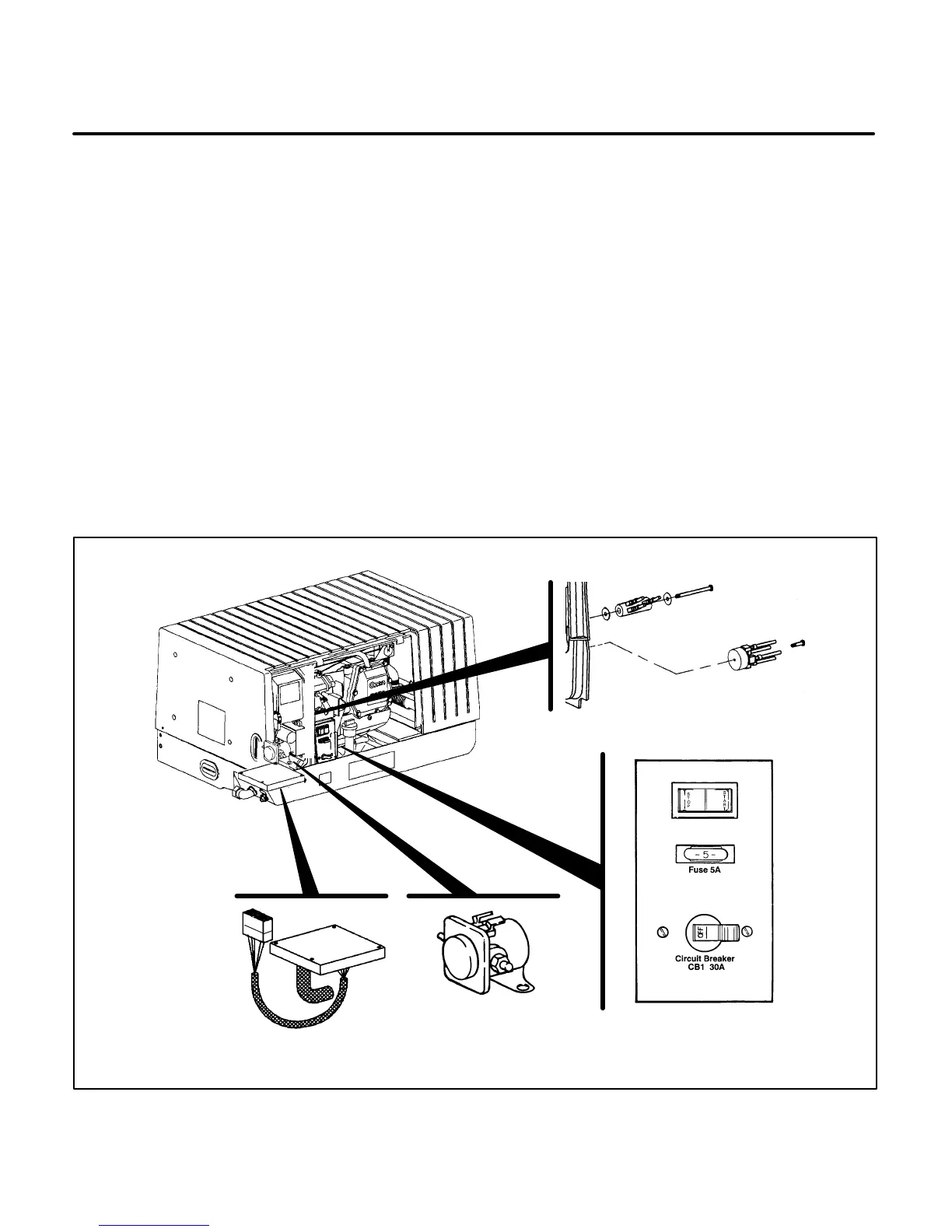
CONTROL DESCRIPTION
The control circuitry consists of the following com-
ponents. See Figure 7-1.
• Panel mounted Start/Stop Switch (S1)
• Start Solenoid (K1)
• Control Fuse (F1)
• Circuit Breaker (CB1)
• Control Assembly (A1)
• Optional Remote Start/Stop Control (A2, A3)
• Battery Charge Resistor (R1)
• Rectifier Bridge (CR1)
• Battery Charger Assembly (VR2)
• Transformer (T1)
Start/Stop Switch (S1)
The Start/Stop switch (S1) is a single-pole double-
throw (SPDT) rocker type switch used for starting or
stopping the genset. Holding the switch in the Start
position will initiate engine cranking. Pushing the
switch to the Stop position will initiate the stop func-
tion. The switch will automatically return to the cen-
ter (Run) position when released.
M1899-3s
CONTROL
ASSEMBLY A1
START RELAY K1
BATTERY CHARGE
RESISTOR R1
BRIDGE RECTIFIER CR1
CONTROL PANEL
FIGURE 7-1. SPEC A CONTROL COMPONENT LOCATIONS
 Loading...

