6-10
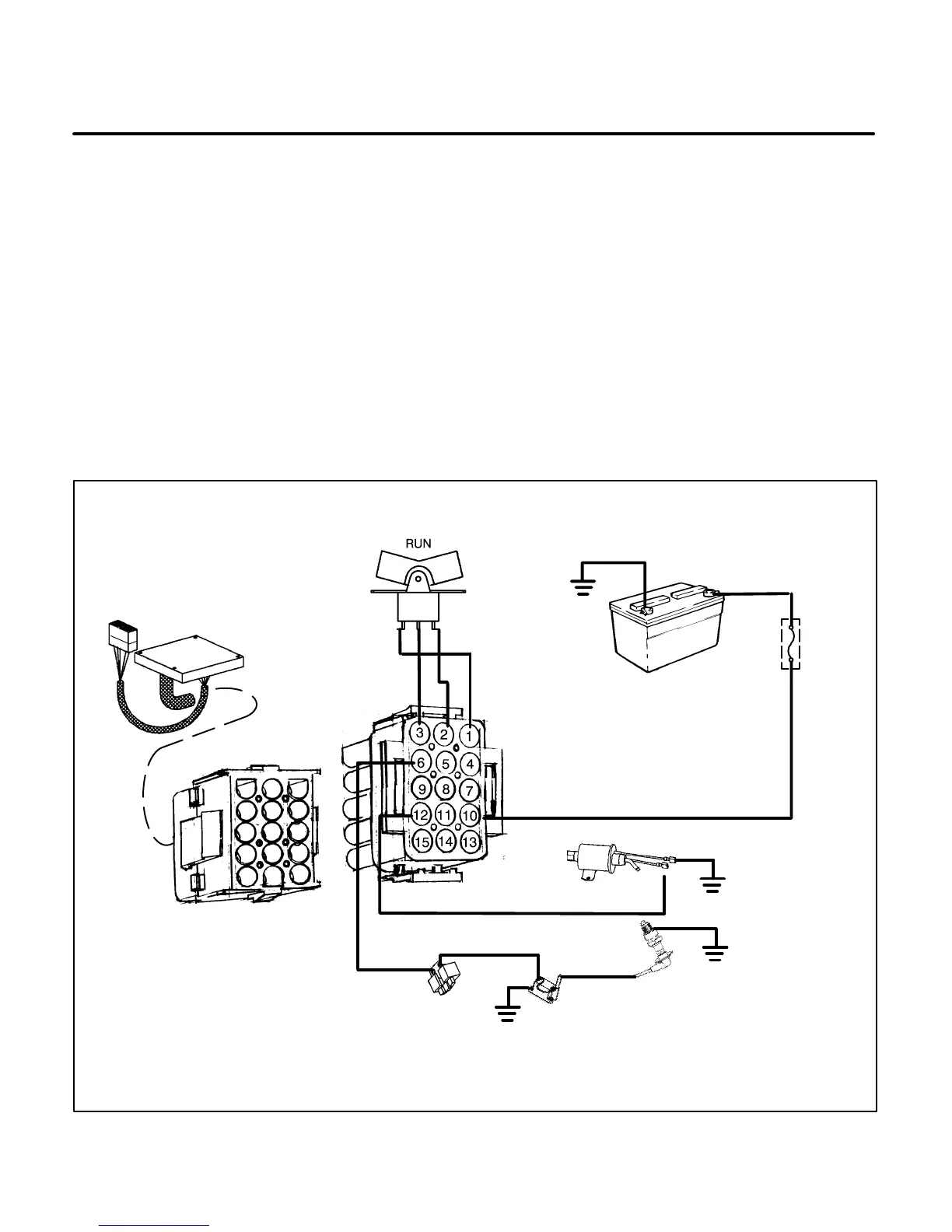
Spec A Run Mode
When the engine starts, release the Start/Stop switch and it will return to the center Run position. The following events
occur:
• Control assembly (A1) opens the circuit to the start solenoid (K1), which opens the circuit to the starter motor
(M1) to stop cranking. Control assembly (A1) also opens the field flash circuit to AVR pin 7.
• Voltage from the battery, used to power the control assembly (A1) and the fuel pump (E2), is replaced with output
voltage from the generator charge winding B1-B2. (Refer to
Battery Charge Mode
on page 6-12.) The control
assembly senses this output for the start disconnect function.
• Remote run output is energized through the control assembly (A1) to power the time meter, battery condition
meter and run lamp in the optional remote control.
• Voltage from the generator Q1-Q2 winding provides power to the voltage regulator VR1 to use for supplying field
current to the generator. (Refer to
Generator AC Output Mode
on page 6-29.)
ES2017-3s
BATTERY BT1
FUSE F1
CONTROL ASSEMBLY A1
START/STOP SWITCH S1
SPARK PLUG E1
FUEL PUMP E2
IGNITION
COIL T1
MAGNETO
IGNITION G2
J1 CONNECTOR
P1 CONNECTOR
FIGURE 6-6. SPEC A RUN MODE
 Loading...

