7-6
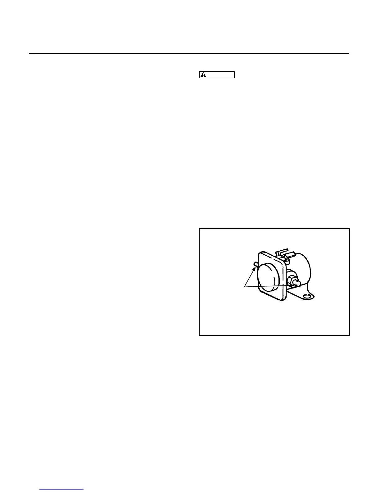
Start Solenoid (K1)
A check can be made by measuring the resistance
of the coil terminals I and S (Figure 7-4). With the
harness leads removed, the coil should read be-
tween 3 and 5 ohms. If an abnormal reading is mea-
sured, replace the Start Solenoid.
If the coil checks good and a problem with the sole-
noid is still suspected, remove the leads from the
side terminal posts. An open circuit should be mea-
sured between the side terminal posts with the coil
de-energized. With 12 VDC applied across the coil
(I and S terminals) the solenoid should be ener-
gized and continuity should be measured between
the side posts.
Control Assembly (A1)
The Control Assembly consists of a printed circuit
board with components and relays that are potted
(encapsulated in a nonconductive material) to pro-
tect them from moisture. It is difficult to isolate indi-
vidual components on the control assembly for test-
ing. Use Section
6. Troubleshooting
to identify pos-
sible problems in the control circuit. If a problem
with the Control Assembly is suspected, use the
control circuit board tester if available, or check the
control outputs with a voltmeter. Figure 7-5 on Page
7-7 shows the Control Assembly and the P1/J1
connectors. Voltages can be checked using a volt-
meter with long test prods.
WARNING
Electrical shock can cause severe
personal injury or death. Do not touch the volt-
meter or any wiring when the genset is operat-
ing. Attach and remove meter leads only when
the genset is stopped.
Tables 7-1 and 7-2 on Page 7-7 list the control out-
puts at the P1/J1 connector plug for each control
mode. Measure control output voltages between
the connector pin listed and ground. Refer to the
correct chart for Spec A and for Spec B models.
Battery B+ voltage must be present at the Control
Assembly J1-10/P1-10 at all times. If battery volt-
age is present at the J1-10/P1-10 connector and the
control outputs are not present, check the J1/P1
connector and the Start/Stop switch (S1). If the con-
nector and switch check good, replace the Control
Assembly with a new Control Assembly and re-
check genset operation.
TERMINAL
POSTS
I
S
START RELAY K1
FIGURE 7-4. SOLENOID CHECK
 Loading...

