11451 Belcher Road South, Largo, FL 33773 • USA • Tel +1 (727) 447-6140 • Fax +1 (727) 442-5699 • sales@onicon.com
F-4600 With LCD Flow Meter Manual 06/18 - 2020-3 / 35874 Page 13
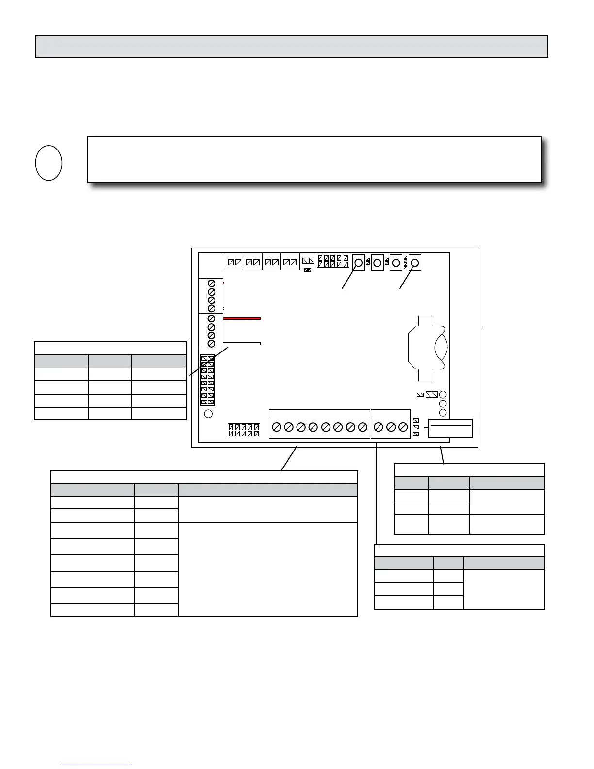
Remote (internal) Temperature Sensor
Name Terminal # Description
1000 ohm TB3-1 RTD signal wire
Not used TB3-2 No Connection
Not used TB3-3 No Connection
1000 ohm RTD TB3-4 RTD signal wire
* This sensor must be in the same
pipe as the ow sensor.
IMPORTANT NOTE
Open isolation valves, leak test and purge the piping system of air prior to wiring the meter.
Power and Signal Inputs (18 - 22 AWG wire)
Name Terminal # Description
24V AC/DC (+) TB1-1
20 - 28 VAC/DC, 50/60 Hz, 5 VA max.
24V AC/DC Common (-) TB1-2
Aux I/O # 1 (+) TB1-3
Congured as either input or output at factory.
Output rating
Pulse Output:
Pulse duration: Selectable 50, 100, 500, or 1,000 ms
Contact ratings: 50 mA, 30 VDC max.
Analog Output (AUX I/O # 3 only):
Selectable: 4-20 mA, 0-10 VDC, 0-5 VDC
Input rating
For use with open collector sinking and dry contact
outputs only.
Pulse duration: 50 ms min.
Sinking Current: 10 mA max.
Aux I/O # 1 (-) TB1-4
Aux I/O # 2 (+) TB1-5
Aux I/O # 2 (-) TB1-6
Aux I/O # 3 (+) TB1-7
Aux I/O # 3 (-) TB1-8
RS485 (20 - 24 AWG wire)
Name TB4 Description
RS485 B (+) TB4-1
RS485 Unit Load = 1/4
Recommended Devices
per Segment = 32
RS485 A (-) TB4-2
RS485 Common TB4-3
RS485 Termination Resistor
Name JMP5 Description
120 ohm Position 1
Jumper Position 1 & 2
= 120 ohms
120 ohm Position 2
None Position 3 Jumper Position 2 & 3
= No Termination
3.4 POWER AND SIGNAL WIRING CONNECTIONS
The F-4600 is provided with 4 glands on the right hand side of the enclosure for power and
signal cables. Each includes a strain relief for securing the cabling and a sealing cap. The power
cable should enter the enclosure through the bottom gland. Do not remove the sealing caps from
unused cable glands.
1 2 3 4 5 6 7 8 1 2 3
10
9
H5
SERIAL
TB3
TB2
H3
4321 4321
1 2 1 2 1 2 1 2
TB8
TB7 TB6
TB5
SW6 SW7 SW2 SW1
C34
C33
R6
DS3
R8
H2
SERIAL
2
1
GRD
DS2
R60
3
JMP5
1
CAUTION
INSTALL + SIDE UP
CR2032 BATTERY
BAT1
Internal RTD
(Flow)
External RTD
24V AC/DC (+)
24V COMMON (-)
AUX 1 (+)
AUX 1 (-)
AUX 2 (+)
AUX 2 (-)
AUX 3 (+)
AUX 3 (-)
RS485 (+)
RS485 (-)
RS485 COMMON
TB1 TB4
COMMISSIONING MICROPROCESSOR
RESET
RS485 Termination
1 - 2 = 120 Ω
2 - 3 = None
System-40-BAC Enclosure Label
1048 / 33354
02-15
11451 Belcher Road South, Largo, FL 33773 • USA • Tel +1 (727) 447-6140 • Fax +1 (727) 442-5699
www.onicon.com • sales@onicon.com
Actual Size - 4.125” x 2.875”
Cutline
 Loading...


