11451 Belcher Road South, Largo, FL 33773 • USA • Tel +1 (727) 447-6140 • Fax +1 (727) 442-5699 • sales@onicon.com
F-4600 With LCD Flow Meter Manual 06/18 - 2020-3 / 35874 Page 9
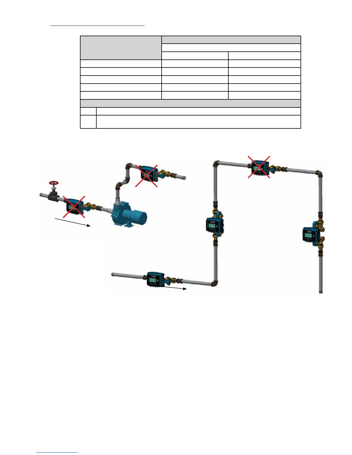
A. This is a recommended position for the ow sensor.
B. Avoid installation locations where air can become trapped in the piping system.
C. This is an acceptable installation location for closed loop pressurized systems.
D. Do not install the sensor downstream of modulating valves or partially open valves.
Fully open isolation valves (e.g. ball valves) are OK.
E. Do not install the ow sensor at the inlet of a pump. To prevent cavitation, the
minimum operating pressure at the inlet of the meter must always exceed the pressure
drop across the meter. Refer to Appendix A-3 for calculating pressure the drop at
different ow rates.
F. Avoid installing the meter downstream of multiple bends out of plane with each other
where there are less than 10 diameters of straight unobstructed pipe between bends.
A
B
C
D & E
F
Flow Direction
Flow Direction
STRAIGHT RUN REQUIREMENTS
Upstream Obstruction
Minimum Upstream Straight Run Required (Pipe Diameters)
Meter Size
0.5 - 1.0" 1.25 - 2.5"
Single Elbow 0 0
Expander / Reducer 0 0
Coil, Upstream 3 3
Isolation Valve, 2 Position 3 5
Control Valve 10 15
Notes:
1 Straight run is based on use of manufacturer provided couplings
2 Avoid the following obstructions where possible: Modulating valves, pump discharge, multiple
elbows out of plane.
A
 Loading...


