CU004/007 Calibration unit
15
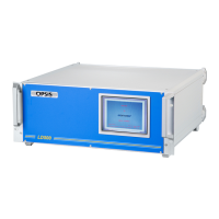
The cable is connected at position 12 in figure 3.2 as follows (connector seen as in this fig-
ure):
Figure 3.4 shows the cable between the calibration unit and the receiver/mirror box. It is to
be used in applications where the calibration path is an integrated part of the measurement
path, as is the case in an ER070 and an ER080 emitter/receiver, and in a configuration con-
sisting of an ER060/ER062 emitter/receiver and a mirror box MB60A. The fibre switch
option (and thus the cable) is not used in configurations with separate calibration paths or
for add-on calibrations using fixed calibration cells in front of the receiver.
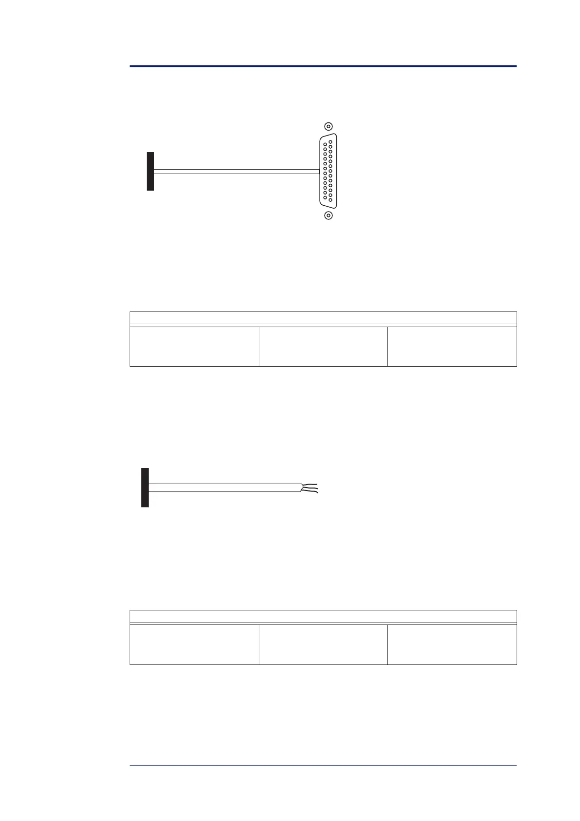
The cable is connected at position 11 in figure 3.2 as follows (connector seen as in this fig-
ure)
:
The cable between the analyser and the calibration unit
left terminal black ground (GND)
mid terminal red receive (RX)
right terminal brown transmit (TX)
The cable between the calibration unit and the fibre switch motor
left terminal black 0 V (common)
mid terminal red monitoring path solenoid
right terminal brown calibration path solenoid
igure 3.3. The cable between the analyser and the calibration unit.
Connected
in the CU
Pin 2 RX
3 GX
7 GND
DSUB 25p
female
igure 3.4. The cable between the calibration unit and the fibre switch motor.
Connected
in the CU
0 V black
Monitoring path brown
Calibration path red