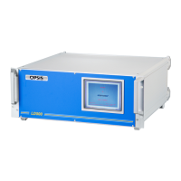
Light adjustment kit LA060
25
5. Adjust the direction of the beam, so it is centred in the outgoing opening. This oper-
ation may depend upon the model of transmitter being installed. See drawings for
transmitter and receiver adjustment.
6. Use the display for optimising the light level.
7. Optimise the receiver unit focus and direction. Light level is indicated on the receiv-
er electronic unit display.
8. Finally, switch back to the ordinary fibre, enter the invisible mode
of the light opti-
mise menu, and fine tune the signal. The dB scale is a logarithmic scale. 3 dB units
more means a doubling of the light level. 10 dB is a factor of 10.
6.3 Measure light throughput to
ensure status of fibre or light
transmitter (version 1.2 and up)
If there is a question of the quality of the optical throughput, use the LA060 to measure the
intensity of the light. Connect one end of the fibre into the LD500 laser output, the other
end into the upper right connector on the LA060. Depending on the output intensity of the
laser, readings of 30-60 dB are normal. Compare the reading with a short fibre of the same
type. Difference between the two readings should typically not exceed 1 dB. If this is the
case, one of the fibres may be damaged.
An alternate way of doing this test is to use the laser output of the LA060 instead of the
output from the LD500. This can only be done if both fibre ends are close.
These tests can also be done on the CF120 communication fibres. (Recommended).
The transmitters on the CC202L card and the RC101L card should output 13 dB light level
or more. Even though “link on” can be read on the RC101L display, communication errors
can make the analyser define the connection as not ok.
6.4 Spare parts
• Part no 0400300: 1.5 meter optical fibre for the LA060.
• AA batteries (4 pcs).
Note: Prior to all installations, it is recommended to test the throughput.