Multiplexers and demultiplexers
30
The DIP switch no. 7 is not used. The position of DIP switch no. 8 states if the function
test mode of the switch is active or not. See section 7.2.5, Function test of the switch. Dur-
ing normal operation this switch should be OFF.
7.2.3 RS232 port configuration
The switch is connected to the LD500 analyser via a straight RS232 cable with a male con-
nector in one end (SX side) and female in the other (LD500 side).
7.2.4 Software configuration
The LD500 menu Peripheral control is used to configure the connected switch. From the
Analyser Root menu press [F1] Installation. Press [F2] Measurement setup and finally
[F1] Peripheral control setup to enter this menu.
Use the up and down arrows to point at the row Multiplexers, and press [Enter] to change
Type to the actual type of switch. Connection is “Serial” for the switch and cannot be
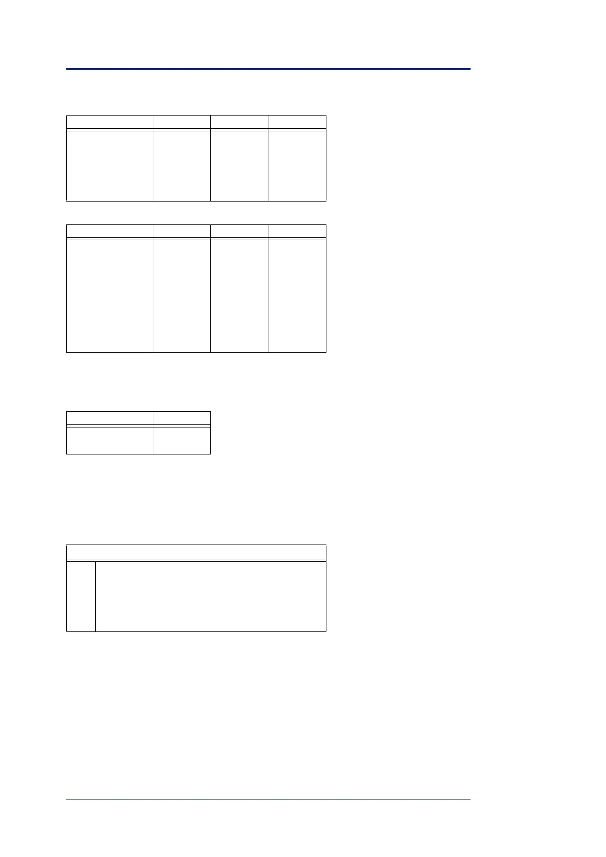
4800 ON ON OFF
9600 OFF OFF ON
19200 ON OFF ON
38400 OFF ON ON
57600 ON ON ON
Function SW4 SW5 SW6
no OFF OFF OFF
SX102 OFF OFF ON
SX103 OFF ON OFF
SX104 OFF ON ON
SX105 ON OFF OFF
SX106 ON OFF ON
SX107 ON ON OFF
SX108 ON ON ON
Test mode SW8
inactive OFF
active ON
Master port, 9 pin Dsub female, DTE
2 TX (Out)
3 RX (In)
4 +12 V
5 GND
7 +12 V
Baud rate SW1 SW2 SW3