CU004/007 Calibration unit
14
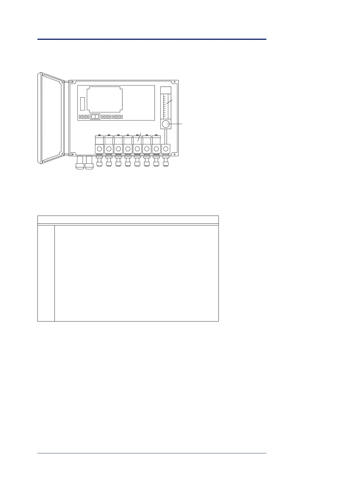
The CU004/CU007 consists of the following main parts, compare figure 3.2:
The tube connectors are designed for 1/4" tube outer diameter. The connecting nuts should
thus be Swagelok SS-402-1.
3.3 Cables
Figure 3.3 shows the serial communication cable between the gas analyser and the control
unit. The signals sent through this cable controls the opening of the different valves, as
well as the switching between the measurement path and the calibration path, if applicable.
CU004/007 main parts
1 Cable inlets
2 Gas inlets from gas cylinders
3 Gas outlet to calibration cell
4 Electrically controlled valve
5 Flow meter
6 Flow regulator
7 Electronics board
8 Mains input
9 Fuse
10 Mains voltage selection
11 Connection for cable to fibre switch
12 Connection for serial communication cable from analyser
igure 3.2. The CU004/CU007 automatic calibration unit, here shown in the CU007 ver-
ion with seven valves.
1
23
4
5
6
7
8101112
9