Assistant Service Manual
OPTIKON 2000
Code 121008S 4-5 Rev. D
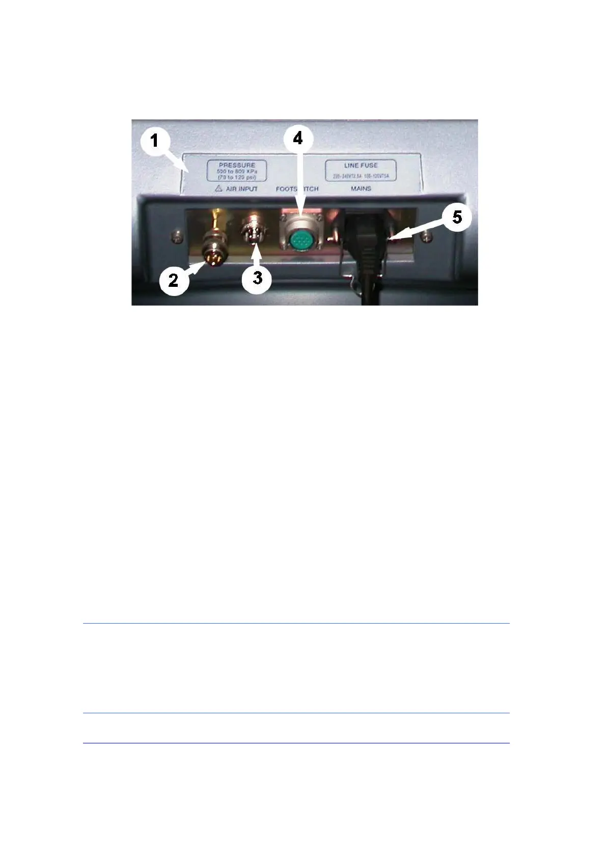
Fig. 3b – Rear panel (bottom)
1) TAG (MARKINGS)
Provides electrical rating and other information as required by IEC 601-1
2)
GAS INLET
Compressed air supply at a pressure of 500-800 KPa
(72 to 116 PSI)
must be
connected to this input. This air is used by the ASSISTANT to operate
Venturi pump and vitrectomy cutter.
3)
IV POLE FOOTSWITCH
The footswitch controlling the IV pole movement must be connected to this
socket.
4) FOOTSWITCH CONNECTOR
This is the system footswitch connector socket. Footswitch depression
activates the ASSISTANT functions.
5) POWER
This is the A.C. voltage input of the module. The mains fuses are located in
this device. The mains voltage selector, on the fuse holder cover, must be
set to the voltage available at your location.
NOTE:
The abbreviations used on the unit and its user interface are defined as follows:
CUT RATE = Vitrectomy cutting rate (cuts per minute)
DIATH = Bipolar diathermy
I/A = Irrigation/Aspiration
IRR = Irrigation