© Optoma
Issue 2.1 July 25, 2018
59
6.3.7 Advanced Splicing
In this menu users define the section of the LED wall that each unit is driving. The menu requires that
that users enter the total LED size, width and height. Also, the portion of the output to be displayed is
defined by the Horizontal and Vertical offset settings.
Wall Width: Total Wall width
Wall Height: Total Wall Height
Hor. Offset: The horizontal position within the total wall space where the image will be place
Ver. Offset: The vertical position within the total wall space where the image will be place
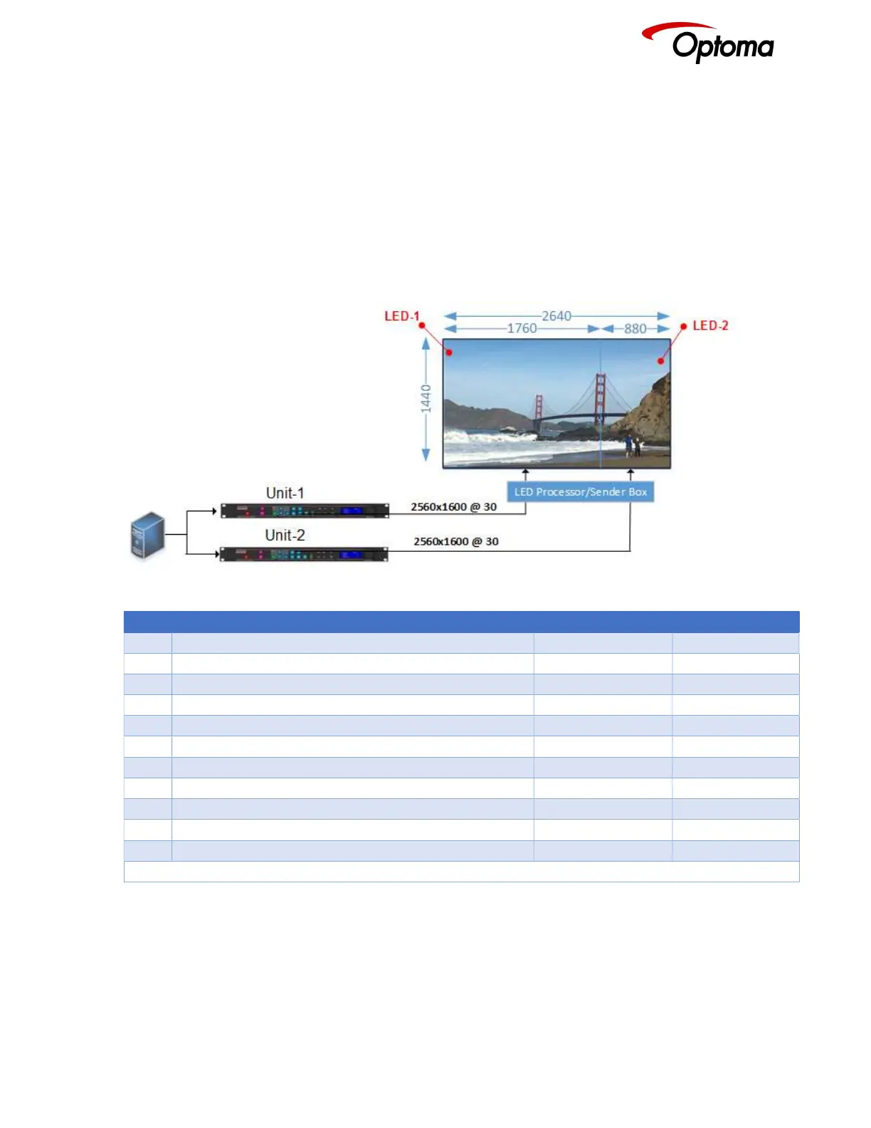
6.3.7.1 Advanced Splicing – 2x1 Example
Figure 8: Advanced Splicing - 2x1 example
STEP MENU ITEM TO MODIFY Unit-1 Unit-2
1 Output>Display Type>Output Mode 2560x1600 2560x1600
2 Output>Display Type> Frame Rate 30Hz 30Hz
3 Output>Display Type>I/O Lock Source Source
4 LED Screen Size> Splicing Zoom On On
5 LED Screen Size> Splicing Width 2 2
6 LED Screen Size> H-Pos 1* 2
7 LED Screen Size> Right Edge 1760 880
8 LED Screen Size> Bottom Edge 1440 1440
10 LED Screen Size> Splicing Advanced Advanced
12 LED Screen Size> Advanced Splicing> Wall Width 2640 2640
13 LED Screen Size> Advanced Splicing> Hor. Offset 0* 1760
* Some steps are skipped, because the values are the same as the default settings after factory reset