Preparation
−
10
−
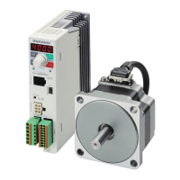
5.4 Names and functions of parts
This section explains the name and function of each part of the motor and driver.
Motor
Illustration shows the electromagnetic brake type.
Protective
Earth Terminal
Motor signal connector
Mounting hole
(4 locations)
Output shaft
Pilot
Motor power connector
Electromagnetic brake connector
Motor cable
Motor
Driver
Communication connector (CN3)
POWER LED (green)
FBLⅡcompatible mode setting switch
(SW1-2)
I/O signal connector (CN5)
Mounting hole (at the back)
ALARM LED (red)
Not used (SW1-1)
External voltage selection switch
(SW2-1, SW2-2)
Motor connector (CN2)
Electromagnetic brake
connector (CN1)
∗
Motor signal connector (CN4)
Internal potentiometer (SPEED)
Acceleration time potentiometer
(ACCEL)
Deceleration time potentiometer
(DECEL)
CHARGE LED
Mounting hole (at the back)
Protective Earth Terminal
Power supply input terminal
Regeneration resistor terminal
(RG1, RG2)
*
Electromagnetic brake type only

 Loading...


