Preparation
−
7
−
2.4 Names and functions of parts
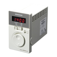
Motor
Parallel shaft • combination type Right angle • geared type
Motor
Output
shaft
Tachogenerator
Mounting holes (four locations)
Protective Earth Terminal
Gearhead
Output
shaft
Gearhead
Motor
Tachogenerator
Mounting holes
(four locations)
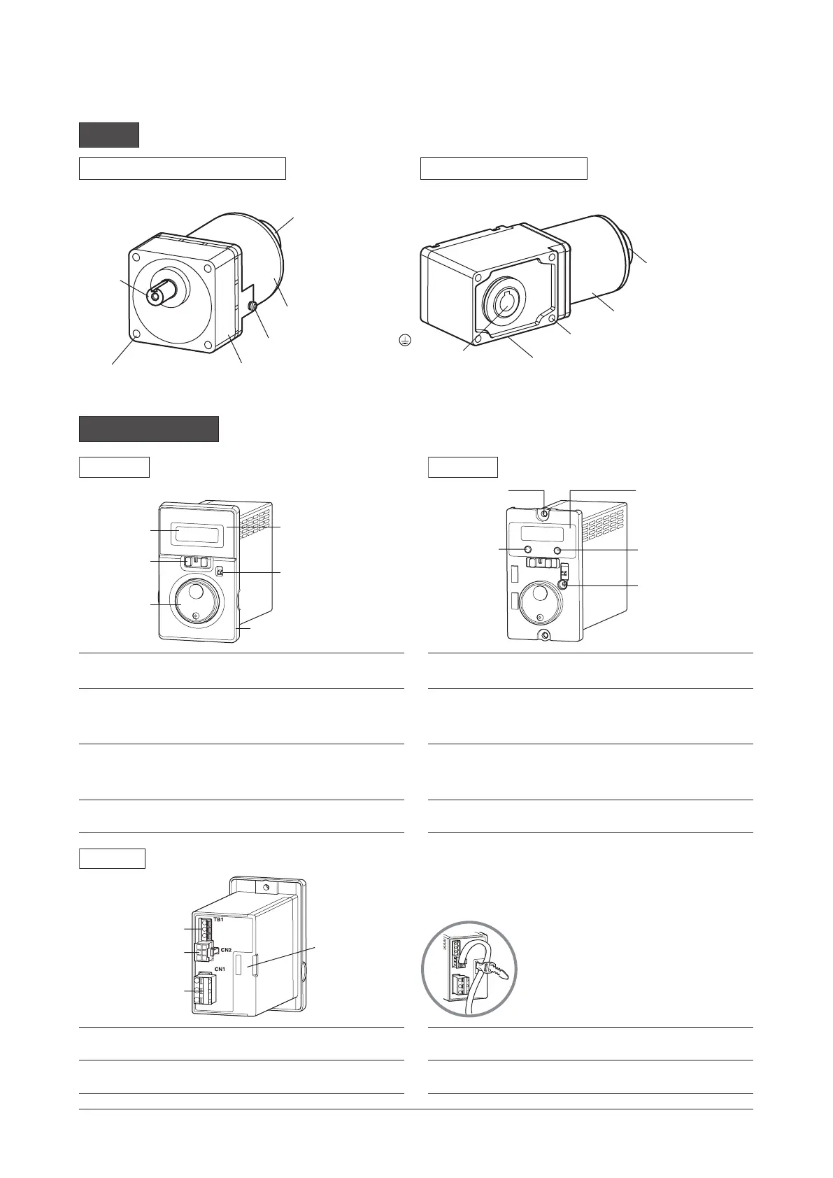
Speed controller
Display
Front panel
Rotation direction
switch
Operation
switch
Setting dial
Protective film
Use after removing
the protective film.
Front side
When the front panel is attached
FUNCTION key
Mounting hole
(2 locations)
ESC key
Acceleration/
deceleration time
potentiometer
Protective film
Use after removing
the protective film.
Front side
When the front panel is removed
Display
This display shows the monitor item, alarms, etc.
ESC key
This key is used to return to the previous level.
Operation switch
Setting the operation switch to the "RUN" side
causes the motor to rotate.
Setting the operation switch to the "STAND-BY"
side causes the motor to stop.
FUNCTION key
This key is used to switch the function.
Setting dial
This setting dial is used to change the rotation
speed and parameters.
After changing, the new value is determined by
pressing the setting dial.
Acceleration/
deceleration time
potentiometer
This potentiometer is used to set the acceleration/
deceleration time.
Rotation direction
switch
This switch is used to change the motor rotation
direction.
Mounting hole
(2 locations)
Installs the speed controller with screws (M4).
Fix as shown in the figure.
This can prevent from giving stress
to the connector terminal caused by
movement of a cable.
Input signal terminal
Motor connector
Power supply
connector
Cable fixing part
Rear side
Motor connector
Connects the connector from the motor.
Input signal
terminal
Connects only when the motor is operated using
external signals.
Power supply
connector
Connects the AC power supply.
Cable xing part
The motor cable can be xed using a supplied
cable-tie.
 Loading...

