DSPEC 50
®
and DSPEC 502
®
Digital Gamma-Ray Spectrometer User’s Manual 932502G / 0618
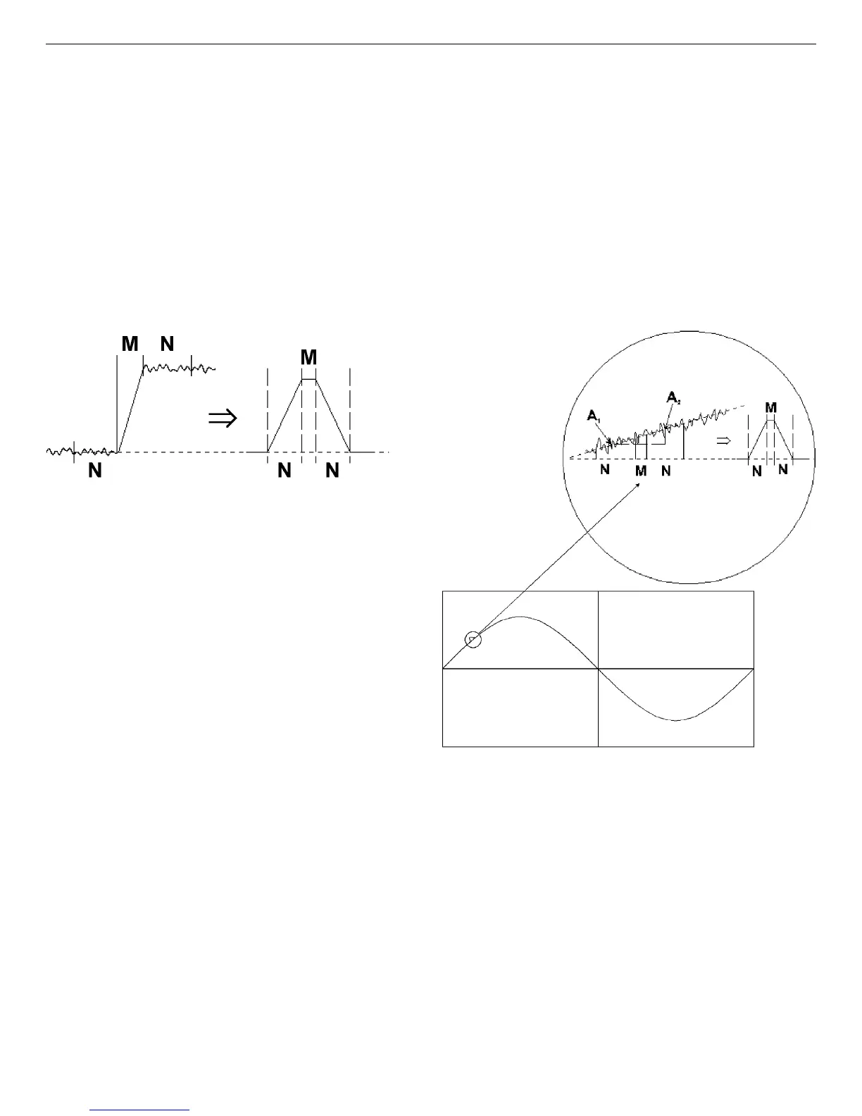
Figure 2. Typical Trapezoidal Weighting
Function (right) Arising from Detector
Preamplifier Output Signal (left).
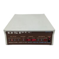
Figure 3. Example of Weighting Function Output
Resulting from the Positive Slope Due to Low-
Frequency Noise (shown as a sine wave).
The ORTEC LFR filter removes most of the microphonic noise by estimating the microphonic-
induced error signal on a pulse-by-pulse basis and subtracting the estimated error signal from the
trapezoid output. As noted above, the error signal is proportional to the slope of the baseline dur-
ing the energy measurement. If the slope is known, then so is the error introduced by the micro-
phonics. An excellent estimate of the slope can be obtained by using the trapezoidal filter itself
to measure the slope both before and after the energy measurement. Since the digital filter is
always sampling the input signal, it is only necessary to store (1) the values measured before the
event is detected, (2) the gamma-ray energy measurement, and (3) the values measured after the
event is detected. The modified trapezoidal digital filter for LFR from an InSight Virtual
Oscilloscope trace is shown in Fig. 4.
A suitably weighted and averaged value of the before and after slope measurement is then sub-
tracted from the energy measurement producing a measurement essentially free of microphonic
noise. Although the inherent increase in the pulse processing time increases the dead time of the
system, the resolution can be greatly enhanced when periodic noise is present.
To switch to LFR mode, click the Amplifier PRO tab under Acquire/MCB Properties..., and
mark the Low Frequency Rejector checkbox (see Section 4.3). Note that you cannot optimize
8