932502G / 0618 2. THE DSPEC 50
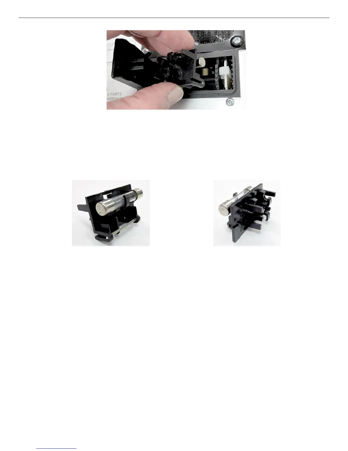
Figure 22. Remove the Fuse Holder.
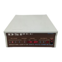
Figure 23. Fuse Holder —
AG Side.
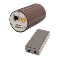
Figure 24. Fuse
Holder — Metric Side.
Figure 23 shows the 100 V/120 V side with an AG fuse in place. In Fig. 24, the fuse holder
has been rotated to show the 230 V/240 V side (facing right) and the two brackets for its
metric fuses.
3) Change the fuse(s), then reinsert the fuse holder fuse side down (thus, for 100 or 120 V ac
line voltage, the single AG fuse should face down; and for 230 or 240 V ac line voltage,
the twin metric fuses should face down). Gently press down until the fuse holder is fully
seated. Close the module door as described in Section 2.2.1.3.
2.2.1.2. Changing the Line Voltage
1) Use the indicator pin to pull the voltage selector card straight out of the module. If
necessary, lift the indicator pin a few millimeters, slide the shaft of a small flat-blade
screwdriver under the top of the pin, and use the screwdriver to gently lift out the card, as
shown in Fig. 25.
2) Unclip the white plastic indicator pin from the card.
31