932502G / 0618 2. THE DSPEC 50
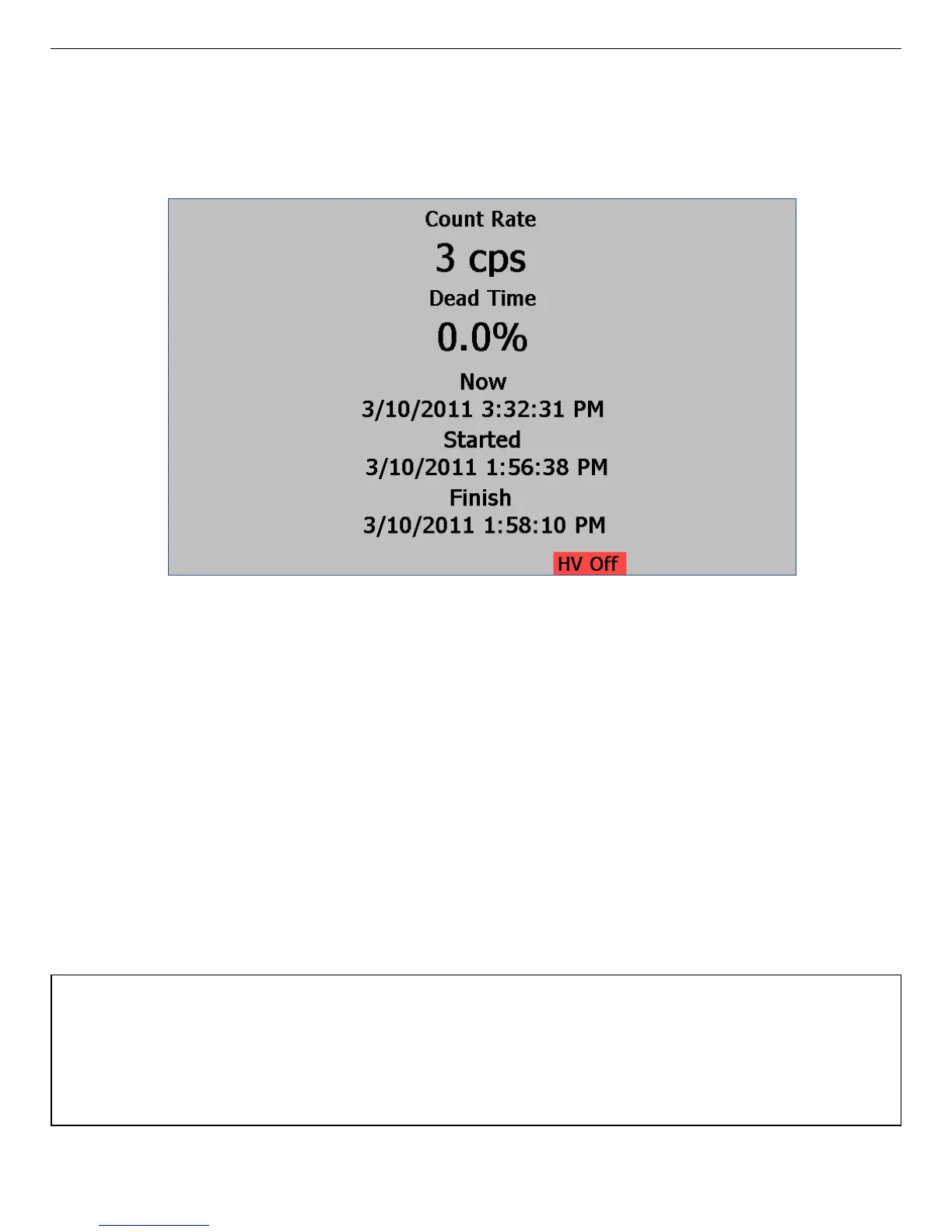
Figure 16. The High-Visibility “Big Numbers” Screen, Showing the HV Off
Indicator.
2.1.5.4. The Big Numbers Screen
The Big Numbers screen makes the current data acquisition status highly visible, even from
across the counting lab. Note the HV Off indicator on the bottom right of Fig. 16.
2.2. Rear Panel
Figures 17 and 18 respectively show the rear panels of the DSPEC 50 and DSPEC 502. Note
that each chassis has only one ac input power module, Ethernet connector, USB connector, SD
card slot, and RESET port. Otherwise, each MCA has the following set of inputs and outputs.
On the DSPEC 502, some connector labels are abbreviated due to space constraints; the
abbreviations are given in parentheses below. See Section 6.1.1 for more detail on the inputs
and outputs.
DIM Multi-pin (13W3) connector supports the SMART-1 and other ORTEC DIM detectors.
No other rear-panel detector connections are required.
CAUTION
To avoid damaging the detector interface module (DIM) cable, be sure to observe the following:
(1) When attaching a detector to the DIM connector, always tighten the cable’s retaining screws
to the rear panel. (2) Before disconnecting the detector from the DIM connector, always power
off the DSPEC-50.
27