932502G / 0618 4, 5. MCB PROPERTIES IN MAESTRO
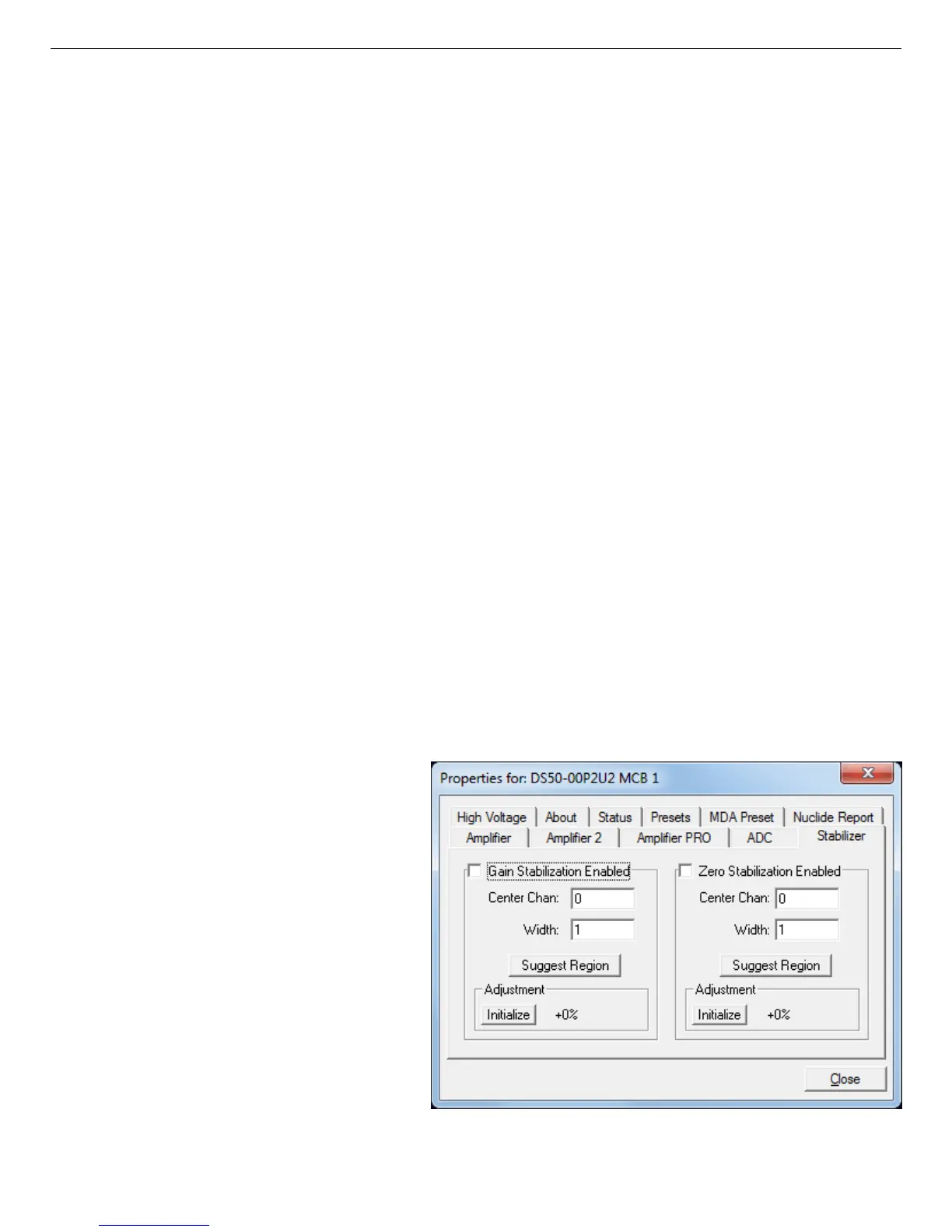
Figure 40. DSPEC 50 Stabilizer Tab.
In MAESTRO, the spectrum window can show either of the two spectra. Use <F3> or
Acquire/ ZDT Display Select to toggle the display between the two spectra. In the Compare
mode, <F3> switches both spectra to the other type and <Shift+F3> switches only the compare
spectrum. This allows you to make all types of comparisons.
Conversion Gain — This sets the maximum channel number in the spectrum. If set to 16384,
the energy scale will be divided into 16384 channels. The conversion gain is entered in powers
of 2 (e.g., 8192, 4096, 2048). The up/down arrow buttons step through the valid settings for the
DSPEC 50.
Upper- and Lower-Level Discriminators — The Lower Level Discriminator sets the level of
the lowest amplitude pulse that will be stored. This level establishes a lower-level cutoff by
channel number for ADC conversions. The Upper Level Discriminator sets the level of the
highest amplitude pulse that will be stored. This level establishes an upper-level cutoff by
channel number for storage.
4.5. Stabilizer
The DSPEC 50 has both a gain stabilizer and a zero stabilizer (see Section D.2). The Stabilizer
tab (Fig. 40) shows the current values for the stabilizers. The value in each Adjustment section
shows how much adjustment is currently applied. The Initialize buttons set the adjustment
to 0. If the value approaches 90% or above, the amplifier gain should be adjusted
so the stabilizer can continue to function — when the adjustment value reaches 100%,
the stabilizer cannot make further corrections in that direction. The Center Channel
and Width fields show the peak currently used for stabilization.
To enable the stabilizer, enter the
Center Channel and Width values
manually or click the Suggest
Region button. Suggest Region
reads the position of the marker and
inserts values into the fields. If the
marker is in an ROI, the limits of
the ROI are used. If the marker is
not in an ROI: For calibrated spec-
tra, the center channel is the marker
channel and the width is 3 times the
FWHM at this energy; and for
uncalibrated spectra, the region is
centered on the peak located within
two channels of the marker and as
51