932502G / 0618 4, 5. MCB PROPERTIES IN MAESTRO
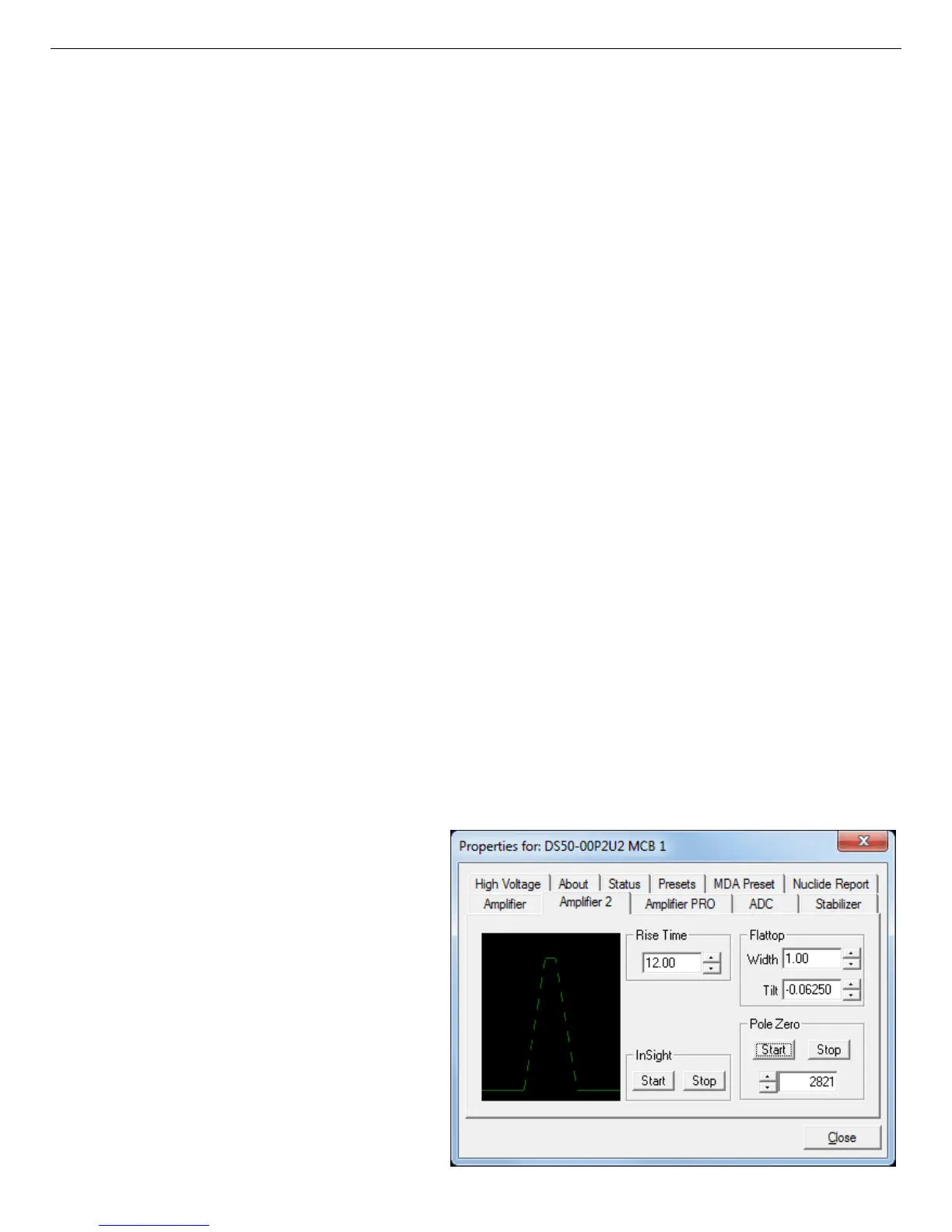
Figure 33. DSPEC 50 Amplifier 2 Tab.
NOTE You cannot optimize with LFR mode enabled; see Section 4.3.
As with any system, the DSPEC 50 should be optimized any time the detector is replaced or if
the flattop width is changed. For optimization to take place, the DSPEC 50 must be processing
pulses. The detector should be connected in its final configuration before optimizing. A count
rate guidance message on the lower-left of the Amplifier page will help you position a radio
active source to deliver the correct count rate for optimization. The Start Auto optimization
button will be disabled (gray) until the count rate is suitable.
Select either the Resistive Feedback or Transistor Reset option and click Start Auto. The
optimize command is sent to the DSPEC 50 at this time and, if the DSPEC 50 is able to start
the operation, a series of short beeps sounds to indicate that optimization is in progress. When
optimizing is complete, the beeping stops.
During optimization, pole zeroes are performed for several rise-time values and the DSPEC 50
is cycled through all the rise time values for the determination of the optimum tilt values. All
values for all the combinations are then saved in the DSPEC 50, so you do not need to optimize
for each possible rise time. Optimization can take from 1 to 10 minutes depending on count
rate, but typically takes 5 minutes.
NOTE Be sure to repeat the optimization if you change the flattop width.
The effect of optimization on the pulse can be seen in the InSight mode, on the Amplifier 2 tab.
Note, however, that if the settings were close to proper adjustment before starting optimization,
the pulse shape may not change enough for you to see. (In this situation, you also may not
notice a change in the shape of the spectrum peaks.) The most visible effect of incorrect
settings is high- or low-side peak tailing or poor resolution.
4.2. Amplifier 2
Figure 33 shows the Amplifier 2
tab, which accesses the advanced
shaping controls including the
InSight Virtual Oscilloscope mode.
The many choices of Rise Time
allow you to precisely control the
tradeoff between resolution and
throughput; see Section 4.13. This
setting affects both the rise and
fall times, so changing it spreads
or narrows the quasi-trapezoid
41
 Loading...